Chapter 02. Dealing with the texture
Section 01: The very basic noise function
In the first chapter, we were drawing on the canvas ourselves. We didn't really care what should have been there without our shader. All our interaction with the input data was limited to adding what we drew to what was already there at the end. This was done using the mix method.
mix(img.rgb, baseColor, shape);
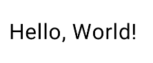
To reinforce this technique, let's try writing a small shader. I would like to create a spoiler effect on text, which you have likely encountered in messengers or social networks. Before pressing the button, white noise is displayed instead of the text. After pressing the button, it gradually transitions into the text.
I will break down the description of creating this shader into two stages. First, we will use a simple black color as the spoiler. Our shader will display black color and then gradually transition to the text. After that, we will add the white noise effect, as there is more to discuss in detail. So, I believe you already have enough knowledge to understand what is happening in this shader:
uniform shader image; vec3 image = parent.rgb; } | |
Shader Code | Result |

Let's now create a method for white noise. The simplest way is to assign each pixel a random (but the same) value for the RGB channels. Thus, we need to write a method that receives the pixel coordinate and returns a random number in the range from zero to one. Such functions are called Hash functions, followed by a postfix indicating the size of the input and the output. If we want to take the pixel coordinate, i.e., its x and y coordinates, and output a single value, we should name the function Hash21. Let's write a simple implementation of such a method:
// Hash function that takes 2D coordinates (x, y) and returns a single float value } |
Shader Code |
Don't focus too much on the actual numbers, they are chosen randomly. This is a pseudo-random number generator. The main idea is to get significantly different values even for neighboring coordinates. The more 'random' this function works, the more natural the result of our shader will look. You can experiment with the values inside this function yourself. The specific implementation in a shader looks something like this:
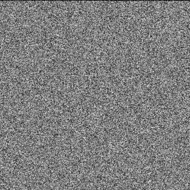
Since the function depends on the coordinates, moving the coordinates far enough can create an effect of randomly moving points across the screen. Just like white noise on old televisions when there was no signal!
In fact, this is one of the simplest implementations, and it has its drawbacks. More advanced noise algorithms are used for more complex visual effects, such as Perlin Noise or Simplex Noise. We will use some of them in the future, but for the current effect, our implementation is perfectly suitable |
Thus, the transition from the state where noise is displayed to the state where only the text is displayed is already written. Now we just need to put everything together and integrate it into the composable code:
uniform shader image;
} vec2 shiftedUv = uv + time*uv; vec3 image = parent.rgb; } | |
Shader Code | Result |
fun ActivityContent() { Box( modifier = Modifier .background(Color.White) .fillMaxSize(), contentAlignment = Alignment.Center ) { var percentage by remember { mutableFloatStateOf(0.0f) } val percentageAnim = animateFloatAsState( targetValue = percentage, label = "") ShaderView( modifier = Modifier .clipToBounds() .clickable { percentage = if (percentage == 0.0f) 1.0f else 0.0f }, content = { Text(text = "Hello, World!", color = Color.Black, fontSize = 24.sp) }, percentage = percentageAnim.value ) } } @Composable fun ShaderView( modifier: Modifier = Modifier, percentage: Float = 0.5f, content: @Composable () -> Unit ) { val shader by remember { mutableStateOf(RuntimeShader(text_from_noise)) } val time by provideTimeAsState(Random.nextFloat() * 10f) Box(modifier = modifier .onSizeChanged { size -> shader.setFloatUniform( "resolution", size.width.toFloat(), size.height.toFloat() ) } .graphicsLayer { shader.setFloatUniform("time", time) shader.setFloatUniform("percentage", percentage) this.renderEffect = RenderEffect .createRuntimeShaderEffect(shader, "image") .asComposeRenderEffect() }) { content() } } | |
Composable code | Result |

Section 02: Simplest Value noise
Actually, even though our result really looks like noise, it is not exactly what it is. That's why I didn't call this method Noise, but named it Hash21. Very often in other literature, you can see that a similar method is simply called Rand (from the word random). So why isn't this noise? The thing is, we have very little control over the result. Essentially, all we have is merely a transformation of two values into some random third value. However, using this pseudo-random number, we can already build a noise function. Let's take a look at one of the simplest implementation of value noise:
float Noise(vec2 p){ | |
Shader Code | Result |
Value noise is a type of gradient noise, which is used extensively in computer graphics to generate natural-looking textures, terrains, and other procedural content. Unlike random noise, which can be harsh and discontinuous, value noise produces smooth, continuous variations that can simulate natural phenomena more realistically.. |
Let's revisit the Noise function step-by-step to see how it implements value noise:
The input coordinates p are divided by the unit size to determine the grid cell ij in which the point lies. xy represents the relative position within the grid cell, normalized to a range of 0 to 1. Then the cosine function is used to smooth the interpolation. This step ensures that the transitions between values are less abrupt and more natural. With the help of early implemented Hash21 we generate pseudo-random values at the corners of the grid cell. These values are what get interpolated to produce the noise value. Mix is a linear interpolation function, which is already familiar to us, blends the values at the corners based on the relative position xy. First, it interpolates along the x-axis (x1 and x2). Then, it interpolates the results along the y-axis to get the final noise value.
Understanding this method can be quite challenging. Believe me, if something is not entirely clear right now, it's not a big deal. The main thing is to understand the overall mechanism and why we need it, how we can apply it. And that's what we're going to do right now! The algorithm for generating noise can usually be found quickly on the internet. There are repositories with many different noise algorithms, and sometimes it's easier to just take and apply different ones to find the one that works best for a specific effect. This doesn't negate the fact that it's better to understand it, I just want to emphasize that, based on personal experience, many such auxiliary functions are often used many times in practice before fully understanding the mechanics of how they work.
Before we continue, let's take a look at the effect we want to achieve in the end. Using this noise, we want to create a disappearance effect for an image (or any other element, such as a button, card, etc.):
To see shader in action you can on my telegr]am post |
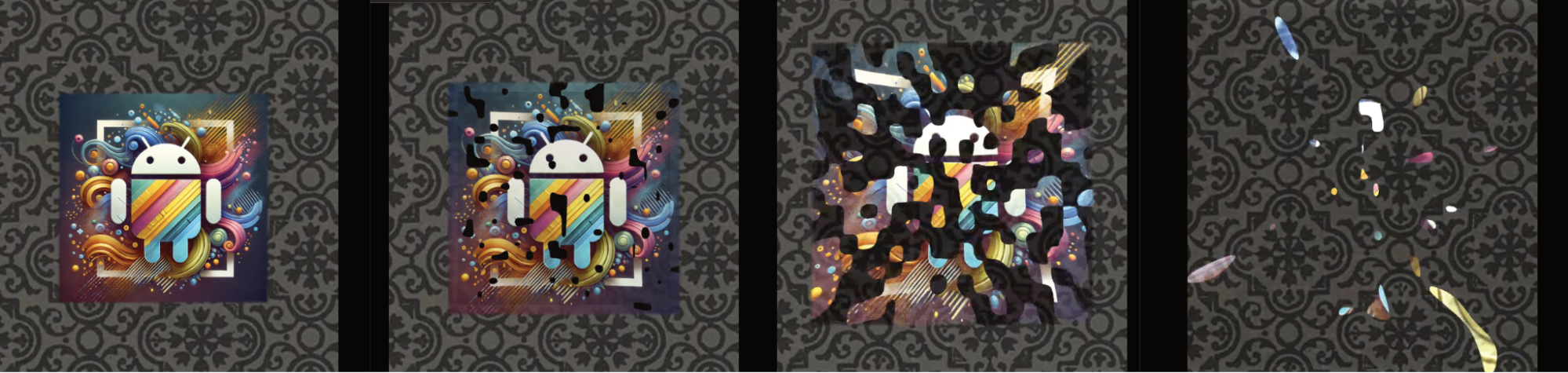
Again, as before, we will use the percentage variable to control the degree of transition from one state to another. That is, if this variable is zero, the image will be displayed without any effect at all. When the variable is at one, the effect is fully completed, meaning nothing will be visible at all.
Now, let's use this variable to modify our noise. This variable will be completely white at the beginning and completely black at the end. However, this won't be a simple color transition; instead, we will use the step method, which we know from before. This way, the 'grains' of our noise will increase. Sometimes it's hard to describe dynamics with words, and it's easier to see it once, but I've included a series of images to make it clearer. I strongly recommend that you write and run this code yourself to fully understand what's happening.
vec4 main(float2 fragCoord) { } | |
Shader Code | Result |

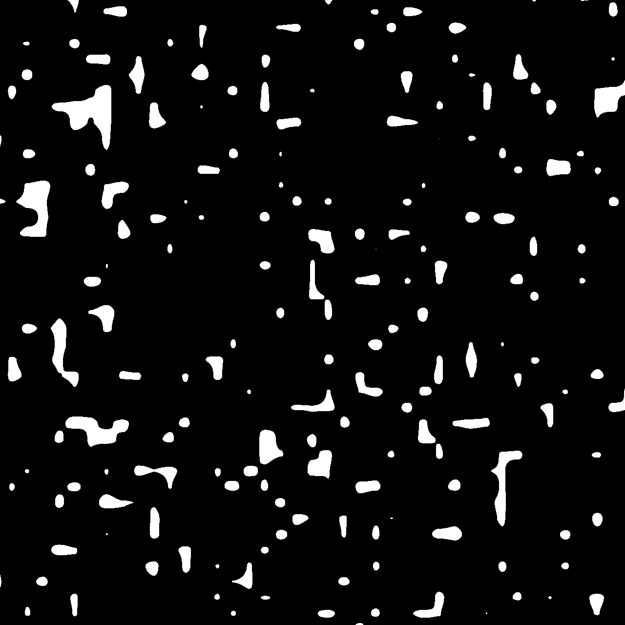
Now let's add scaling. We'll tie it to the same variable and stretch our coordinate grid. If we simply multiply by some coefficient, we'll get an even expansion in all directions, but we want an explosion effect. That is, we want the edges to disperse a bit faster and get slightly distorted. This can be achieved by scaling the coordinates non-linearly, depending on the distance from the center. Since the coordinate center is at the center of the screen, this will give us an interesting effect.
uv *= (1.-percentage*0.2); // just linear scale |
Shader Code |
To obtain the image that should be displayed before applying our effect, we use the eval method, which requires the actual pixel coordinates, not the normalized ones. We usually write something like this: image.eval(fragCoord); This works because fragCoord provides us with the necessary coordinates. However, if we want to scale the image, we need to adjust these coordinates first; otherwise, the image will scale from the top-left corner. We want the zoom to originate from the center. To achieve this, we need to first apply the scale to the coordinates and then shift them by half to the left and up. This looks as follows:
vec2 scaledFragCoords = fragCoord*scale; |
Shader Code |
All that remains is to make the transition from the image when percentage is zero to the noise when percentage is one, and also to add alpha so that the image fades out as it transitions to the noise. Here is how it can be done:
vec3 col = parent.rgb*noise; |
Shader Code |
The shader is ready! But there is a small nuance. Personally, I don't like the artifacts that appear at very large distances from the center (this is due to our non-linear scaling). Therefore, I decided to add a mask. Essentially, this is a square whose edges gradually become smoother as the animation progresses. I cut out only what is inside this square, thereby getting rid of unwanted artifacts. This makes the effect more pleasing to me. However, for this, I had to add another variable, since uv is already occupied. I named it sv and increased it at a slightly different speed and completely linearly. The mask itself is called borders. You can see the full shader code below:
uniform shader image; |
Shader Code |
And a sample possible usage in compose:
@Composable |
Composable Code |
Section 03: Chromatic aberration
Chromatic aberration is perhaps one of my favorite effects. It's remarkably simple to implement, yet it looks incredibly striking. Recently, it's become quite popular in UI design, so let's take a look at how to create it.
Technically speaking, chromatic aberration refers to image distortions caused by the dependency of the refractive index of a medium on the wavelength of the radiation passing through it (aberration is caused by light dispersion). Due to the phenomenon of dispersion, the focal lengths for different wavelengths (rays of different colors) vary and do not converge at a single point, known as the focus.
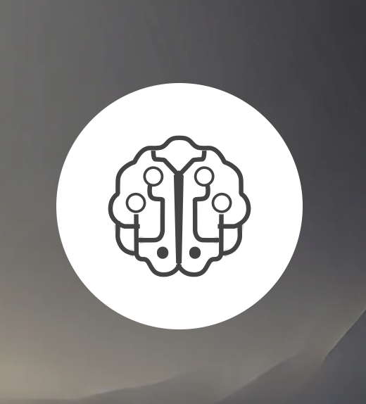
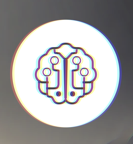
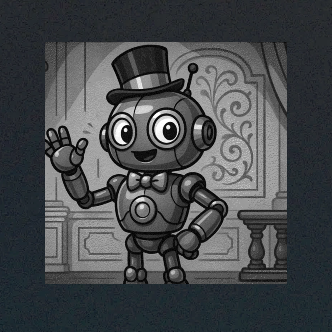
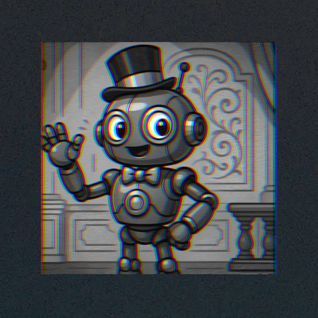
But that's physics. To simulate this effect, without physical accuracy but with a fun and beautiful visual result, you can simply take the red channel and shift it to one side of the image, while moving the blue channel in the opposite direction. And that's it! Here’s what it might look like:
Original image | Chromatic aberration |
Let's now take a look at how this can be implemented technically. We already know how to take an input and simply display it on the shader's 'canvas,' that is, to obtain the original color of each pixel and then work with it. A crucial part of this effect, as with many others related to input deformation, is having control over where exactly we want to project this pixel. So let's start by writing a method that will do almost the same thing as a simple image.eval, but with a bit more control over the position where we retrieve this pixel:
vec4 GetImageTexture(vec2 p, vec2 pivot) { |
Shader Code |
We need to remember that fragCoord represents non-normalized coordinates, meaning it refers to pixel positions. For example, in a component with a size of 20 by 40 pixels, the central pixel would have fragCoord equal to (10, 20). However, we work in a normalized uv system, where we shift the center to the middle of the canvas so that zero is in the center, and the horizontal and vertical values range from -0.5 to 0.5. We then apply an aspect ratio correction, so the vertical values might be slightly more or less, but the concept remains the same. This is why we've always called image.eval with fragCoord.
In the function we wrote, I want to pass uv, so first, we reverse the operation we performed to obtain uv in order to 'return' it back to fragCoord. Then, we shift the center to 0.5, 0.5 (i.e., the center). To summarize, if you call our method like this: GetImageTexture(uv, vec2(0.5,0.5)), you'll get exactly the same result as you would by calling image.eval(fragCoord). But now, we can modify uv and see the corresponding changes, which will become clear in the next section as to why this is necessary.
Let's apply this by adding a small horizontal offset to the UV coordinates:
GetImageTexture(uv + vec2(0.1, 0.0), vec2(0.0, 0.0)); |
Shader Code |
We can see that the entire texture has now shifted to the right. Next, we can create a variable for the final color and call the method three times, each time slightly changing the horizontal offset and selecting only one specific color channel.
float aberrationAmount = 0.05; |
Shader Code |
Now all that's left is to add a percentage value so the effect can be animated — and that's it! That's how easy it is to create such an interesting effect. Below is the full code listing:
uniform shader image; | percentage = 0 percentage = 1 |
@Composable |
Composable Code |
Section 04: Ripple effect
The next effect is quite difficult to demonstrate with a static screenshot, but it looks truly mesmerizing in motion. So just a reminder — you can clone the repository I created specifically for this book, run the project on your phone, and see the effect in action.
The idea behind this effect is that when you tap the screen, a wave radiates outward from the touch point.
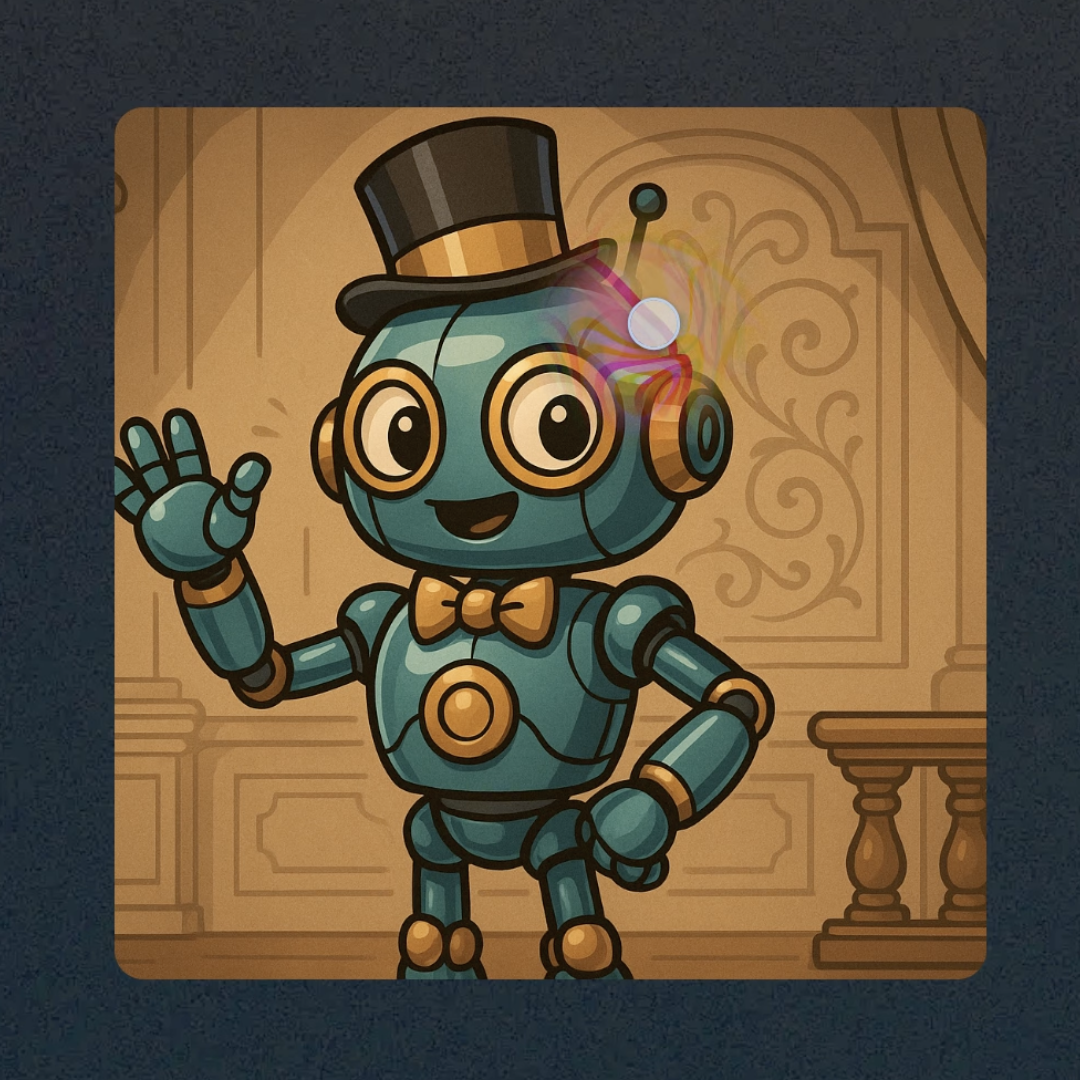
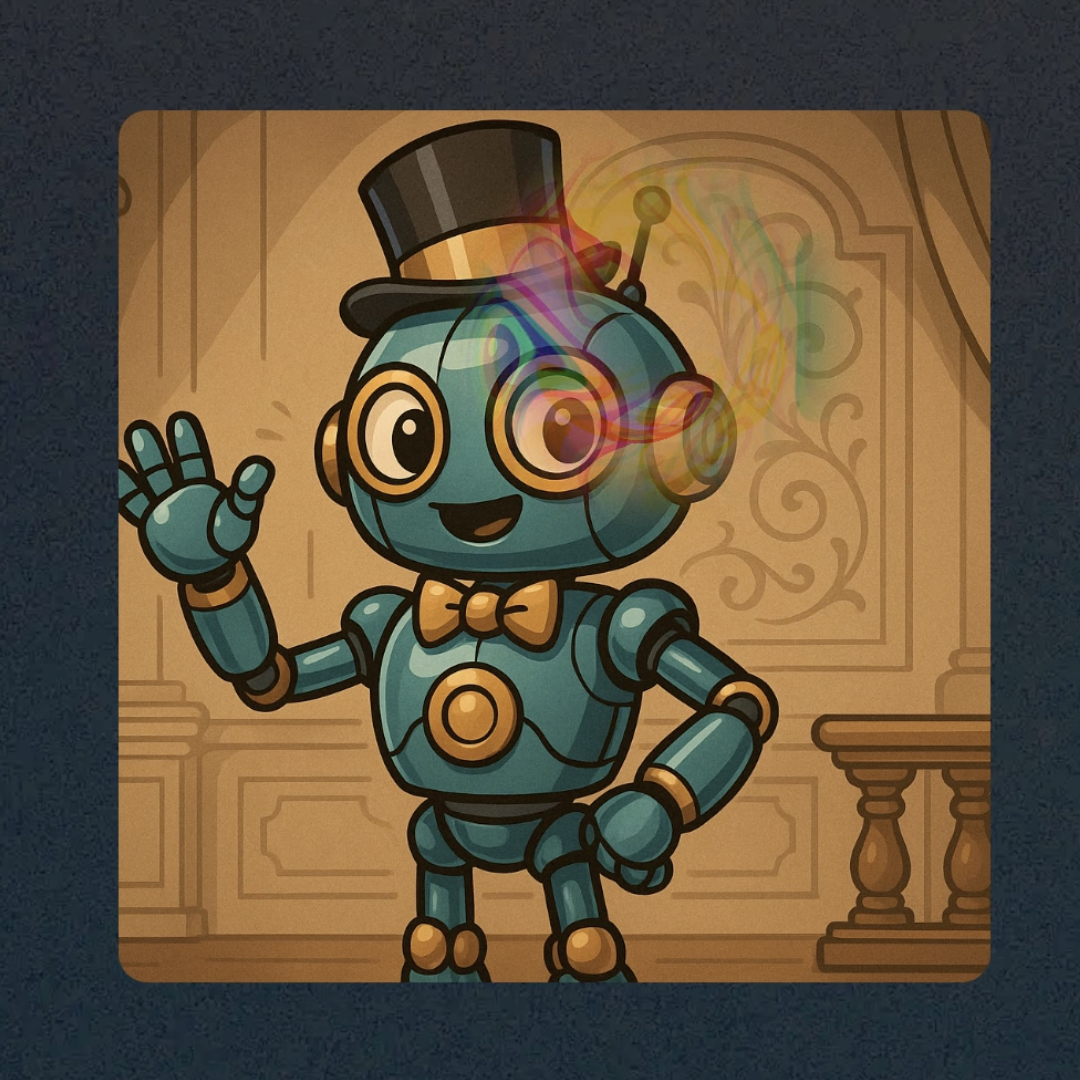
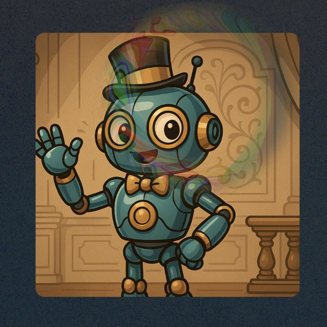
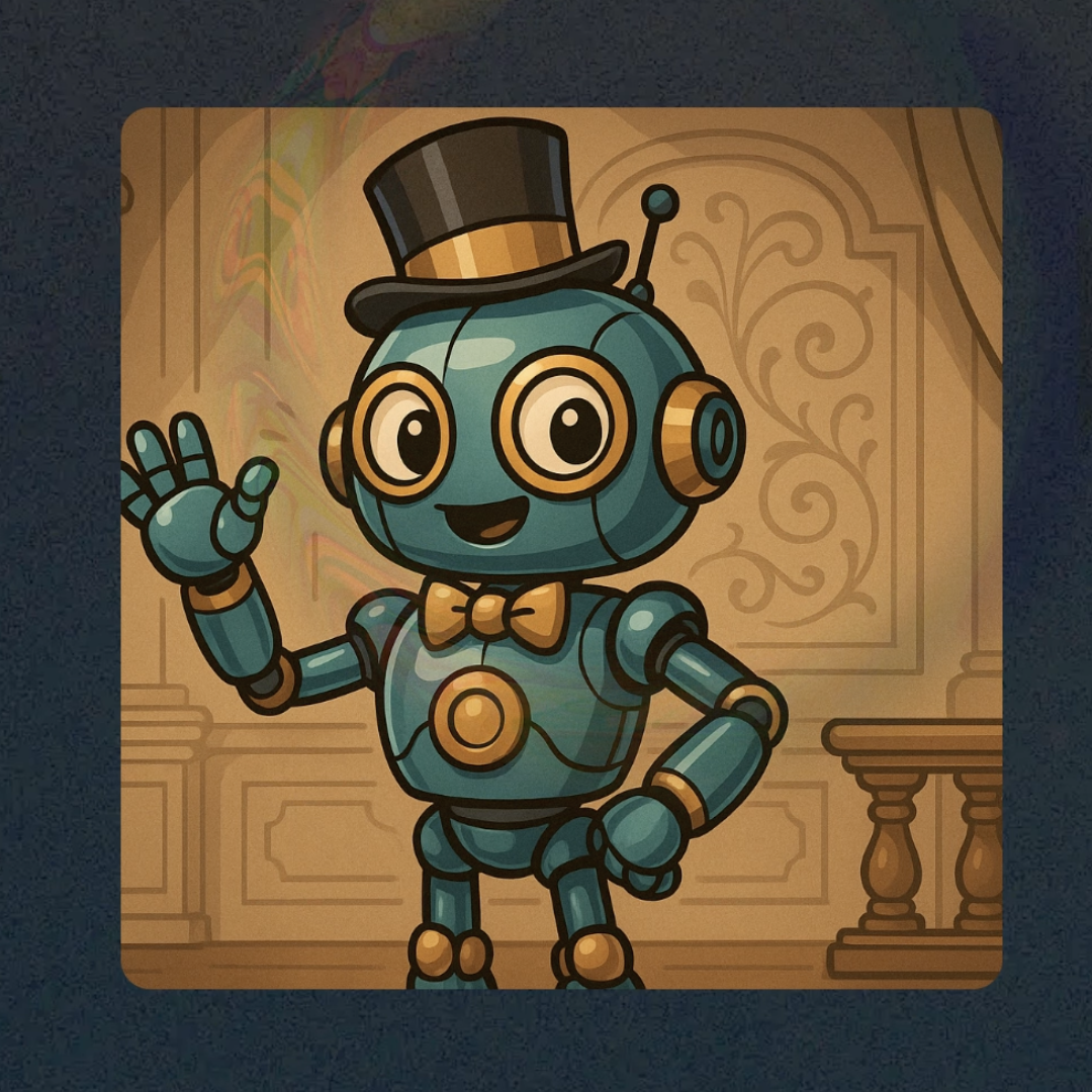
We’ll be using many of the techniques we’ve already covered, with a few modified methods. But before we dive into the shader itself, let’s take a moment to understand the mathematical concept behind the effect.
So, let’s take a closer look at what this effect is made of. I temporarily set a checkerboard pattern as the background to make it more visually clear. Now it’s easy to see that at any given moment, the effect is represented by a ring. Inside this ring, there’s some distortion of the texture, along with other effects like chromatic aberration.
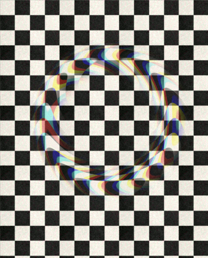
We already know the SDF function for a circle. Just to recap — an SDF (Signed Distance Function) returns zero exactly on the shape’s boundary, and its value increases as you move away from the edge, both inward and outward. Knowing this, creating a ring becomes easy — in fact, we’ve done it several times already back in Chapter One!
All we need to do now is make the radius change based on the current effect progress, which goes from 0 to 1. So, we simply define the final radius we want by the end of the effect and multiply it by the current percentage.
Putting all of this together, we get something like the following:
float CircleSDF(vec2 p, float r) {
| |
Shader Code | Result |

I also moved the coordinate normalization into a separate function, since we’ll need it multiple times in this shader. Additionally, I added a vec2 for the position from which the ring will radiate. For now, you can just use vec2(0., 0.); — I’ll explain how to pass the actual touch position later, when we integrate the shader with Compose.
At this stage, the effect is still quite basic and just looks like a regular ring that expands according to the percentage value passed into the shader.
Now let’s add the texture passed to the shader via the Image parameter, just like we did in the previous section. I also slightly modified the GetImageTexture function — now it can also apply an offset based on the provided center position.
vec4 GetImageTexture(vec2 p, vec2 pivot, vec2 r) { | |
Shader Code | Result |
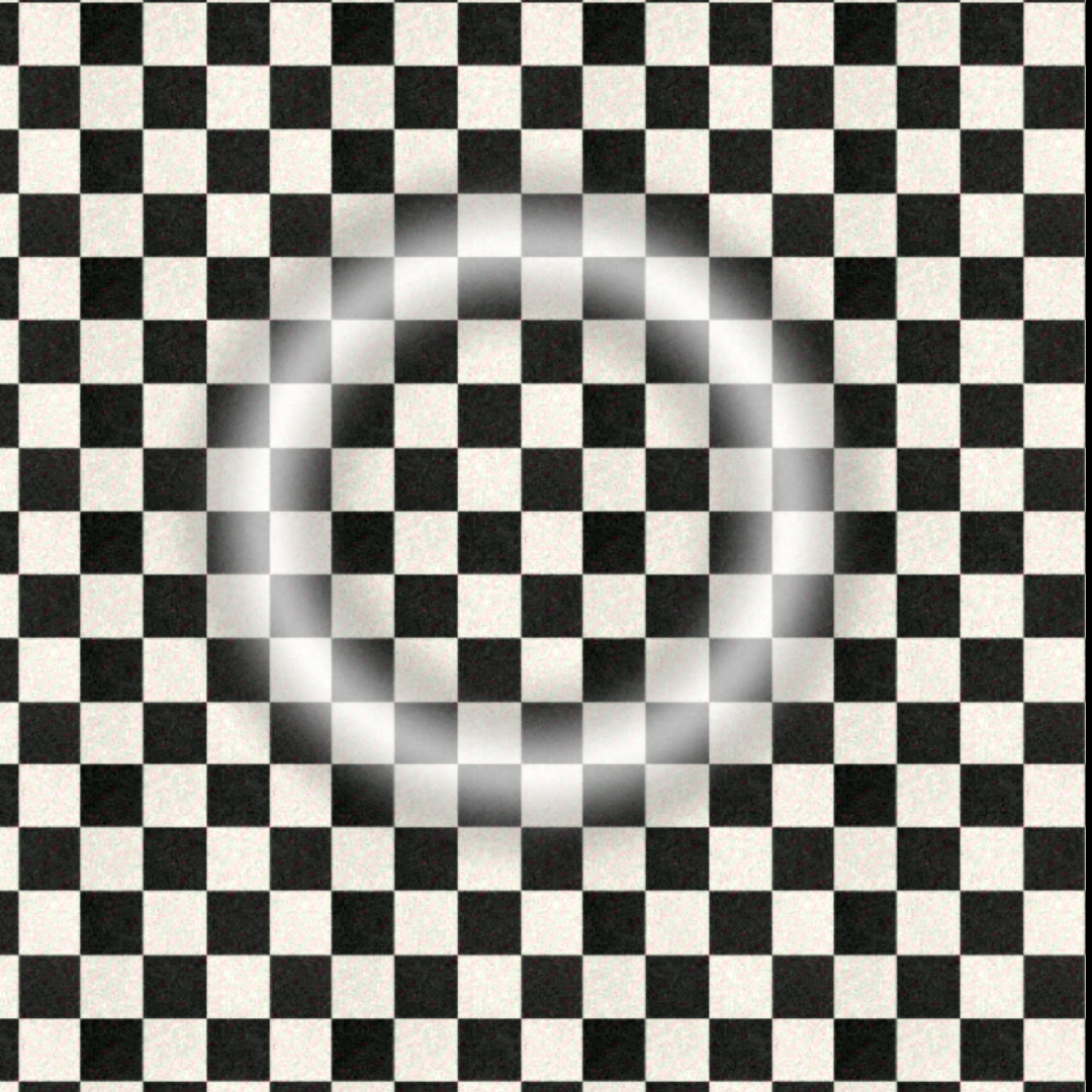
It's important to note that the checkerboard background is simply a texture passed from Compose — it's just an image inside a box with the shader applied. It's not something the shader draws by itself, so this texture can be replaced with any image! We’ll look at how to integrate this shader into Compose later in this section. |
At this point, we already have a mask for our effect and we’re blending the texture with it. The final step is to distort the part of the texture that falls within the mask. We can reuse the same method to fetch the texture, but this time we’ll modify the coordinates where the original image is mapped. This is a very important technique, and I highly recommend taking a moment to fully understand it.
When we sample a texture, we're working with a 2D image where each pixel has a horizontal and vertical position. In the shader, at any given moment, we're processing a specific pixel. When we fetch a vec4 from the texture (under the hood, via the eval function), we're mapping the original texture's coordinates to the ones we provide. So, if we pass in some "deformed" coordinates, the original texture will be distorted accordingly.
For example, try multiplying the position p (which we pass to eval) by 2 — you’ll see the entire image shrink by half, since we’re now mapping the texture onto coordinates that are twice as large.
In our case, we won’t just stretch the image — we’ll add the value of our SDF to the coordinates before sampling the texture. This way, the distortion will only happen within the area defined by the mask, because we’re blending the original image and the distorted one using the mask’s alpha channel.
As a result, we’ll get the following effect:
vec4 Wave(vec2 d, vec2 p) { | |
Shader Code | Result |
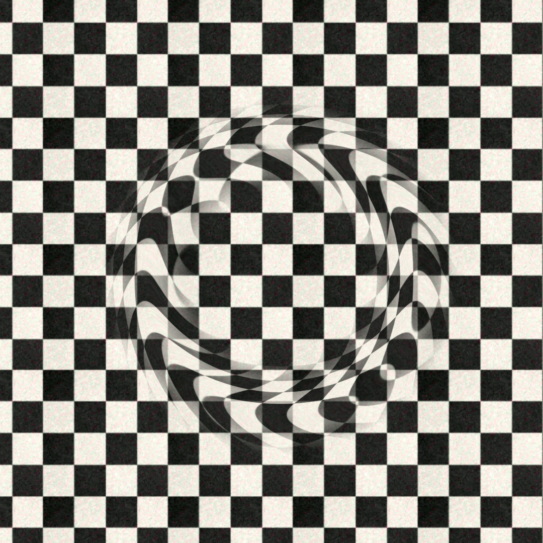
To make the effect more visually appealing, let’s add the chromatic aberration from the previous lesson. I’ve also moved it into a separate function, but the principle remains exactly the same. In the end, we’ll get a ring that looks like this:
vec3 ChromaticAberration(vec2 p, vec2 d, vec2 r) { | |
Shader Code | Result |
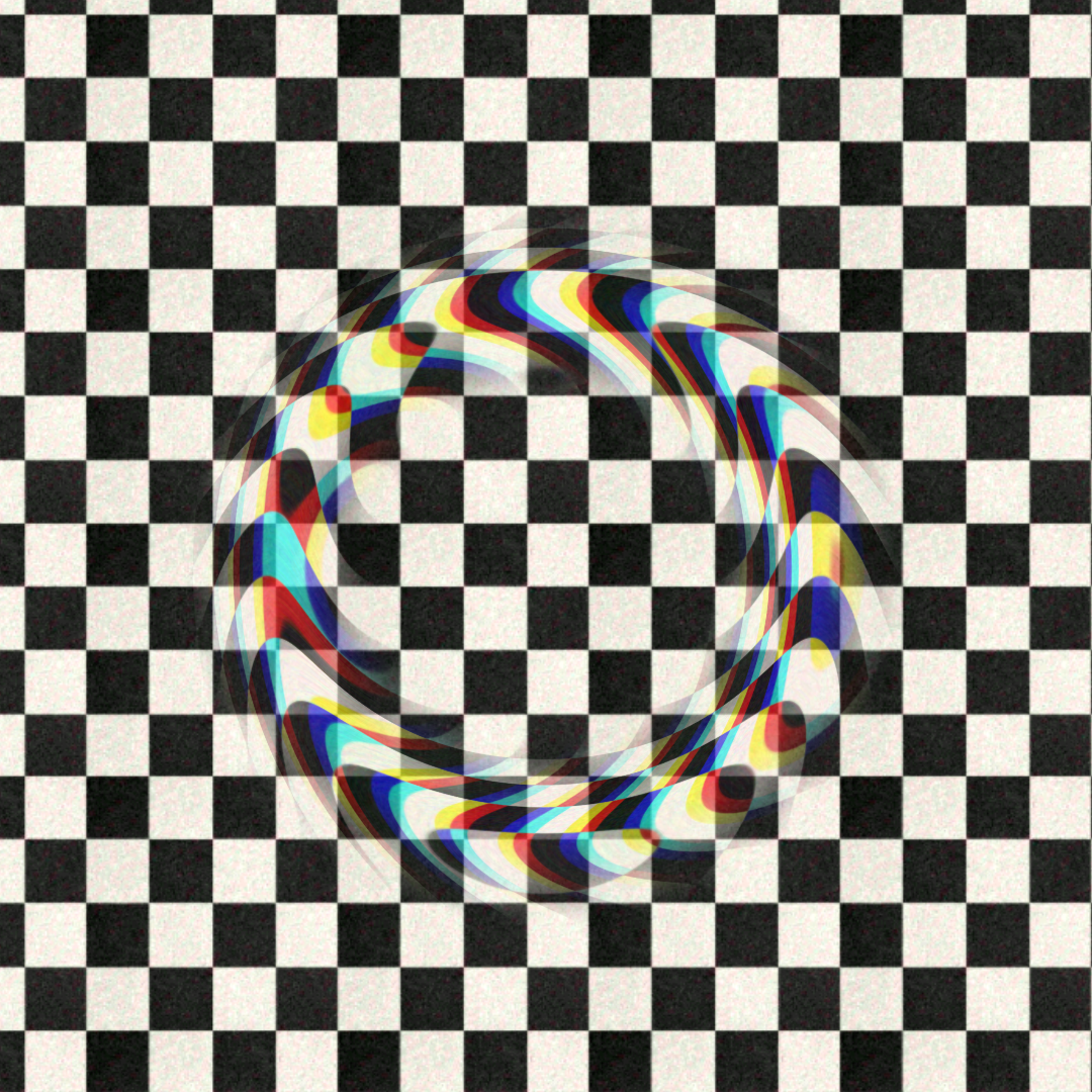
And now it becomes clear why I added the center parameter to getImageTexture. In fact, beyond just this effect, it’s quite common to sample a texture with an offset center in various scenarios. That’s why I recommend keeping and using this version of the texture-fetching function. I’ll be using it throughout the rest of the book.
Now let’s take a look at how to integrate this into Compose. Earlier in this book, I didn’t spend much time on this part, since the basic setup was usually enough: we create a shader, place it inside a Box, attach the shader to the Box, and pass in the necessary parameters. Occasionally, we used things like a time counter.
However, time flows continuously, and for this effect we need to start the animation on touch and end it after some time, once it reaches a progress value of 1. On top of that, we also need to capture the exact position where the user tapped.
Let’s break it down step by step. First, here are the three variables we’ll pass into the shader (in addition to the texture, which is passed as usual):
@Composable
|
Composable Code |
Next, let’s decide how we’ll update the time. I chose to use the lerp function from the Compose utilities. It performs linear interpolation between a start and end value based on a given fraction.
If we call this function repeatedly, each time updating the start value to the current one, we get an exponential decay effect. This means our ring won’t expand at a constant speed — instead, it will spread out with a smooth, easing slowdown:
@Composable |
Composable Code |
Next, we detect a tap on the container — and at that moment, we trigger a new instance of the effect:
@Composable |
Composable Code |
And one last important detail: since the effect needs to apply to the background as well, we must assign that background directly to the container the shader is attached to. If we leave it transparent, as we did in earlier sections, the effect will only appear on the image inside — not on the background.
This is a key point. It's one of the main reasons why implementing effects like background blur or frosted glass is so tricky: the shader doesn’t have access to the content rendered underneath or behind the current element in the view hierarchy. It only works with what's explicitly passed into the target element.
It’s a frustrating limitation that complicates many use cases — but in this particular case, it’s not a big problem. We can simply assign the background directly to the container, and the effect will work as expected.
@Composable |
Composable Code |
That’s it! The full shader code is provided below. Once you’ve had some fun experimenting with it, feel free to move on — there are plenty more exciting effects ahead!
uniform shader image; |
Shader Code |
Section 05: Fade and shrink the list
I'm sure you've often seen the effect where content fades out near the edges of a list. For example, in number pickers that look like spinning drums. And really, there are lots of situations where fading out list content comes in handy. It always looks visually appealing — just take a look at the list on the main screen of the app that comes with this book.
Here's the interesting part: most of the time, this effect is fake! If you're working with a solid background, you can just add two blocks at the edges and fill them with a gradient from fully transparent to the background color. It's a simple but very limited way to achieve the effect.
On the other hand, if you want a proper alpha transition, things suddenly get surprisingly complex — you have to calculate offsets, item positions, and other stuff. And even if you manage to get that working, you’ll still hit a limitation: you can only apply alpha to the whole item. But what if you want to fade only part of the item?
Well, by now you already know enough about shaders to solve that in about 10 lines of code. And that’s exactly what we’re going to do.
But just to show you how powerful this tool in your arsenal really is, I’m going to make things a bit more interesting. Since basic fading is too easy for you now, let’s also stretch the content! Let’s make it not only fade at the edges, but also slightly compress. That way, we’ll get a subtle 3D list effect — not too strong, but just enough to give observant users a little wow moment.
So, let’s start by creating a basic alpha fade-out for the content. What do we need for that? Honestly, if we have vertically normalized coordinates, all we really need to do is calculate the alpha near the edges using smoothstep or any other interpolation method, gradually reducing it to 0 past a certain point.
Instead of using smoothstep, though, let’s try something different — we’ll use an exponential curve, just to mix things up a bit. We’ll write a method for exponential interpolation, normalize the coordinates, and calculate the distance from 0 (the center). We’ll start the fade effect at 0.45. Since our coordinates go from 0.5 at the top to -0.5 at the bottom, using the distance from 0 means we get the effect on both sides with a single calculation.
Back in the third section of the first chapter, we already took a close look at the smoothstep function. Just to recap — it’s a cubic Hermite interpolation, and its graph looks like this:
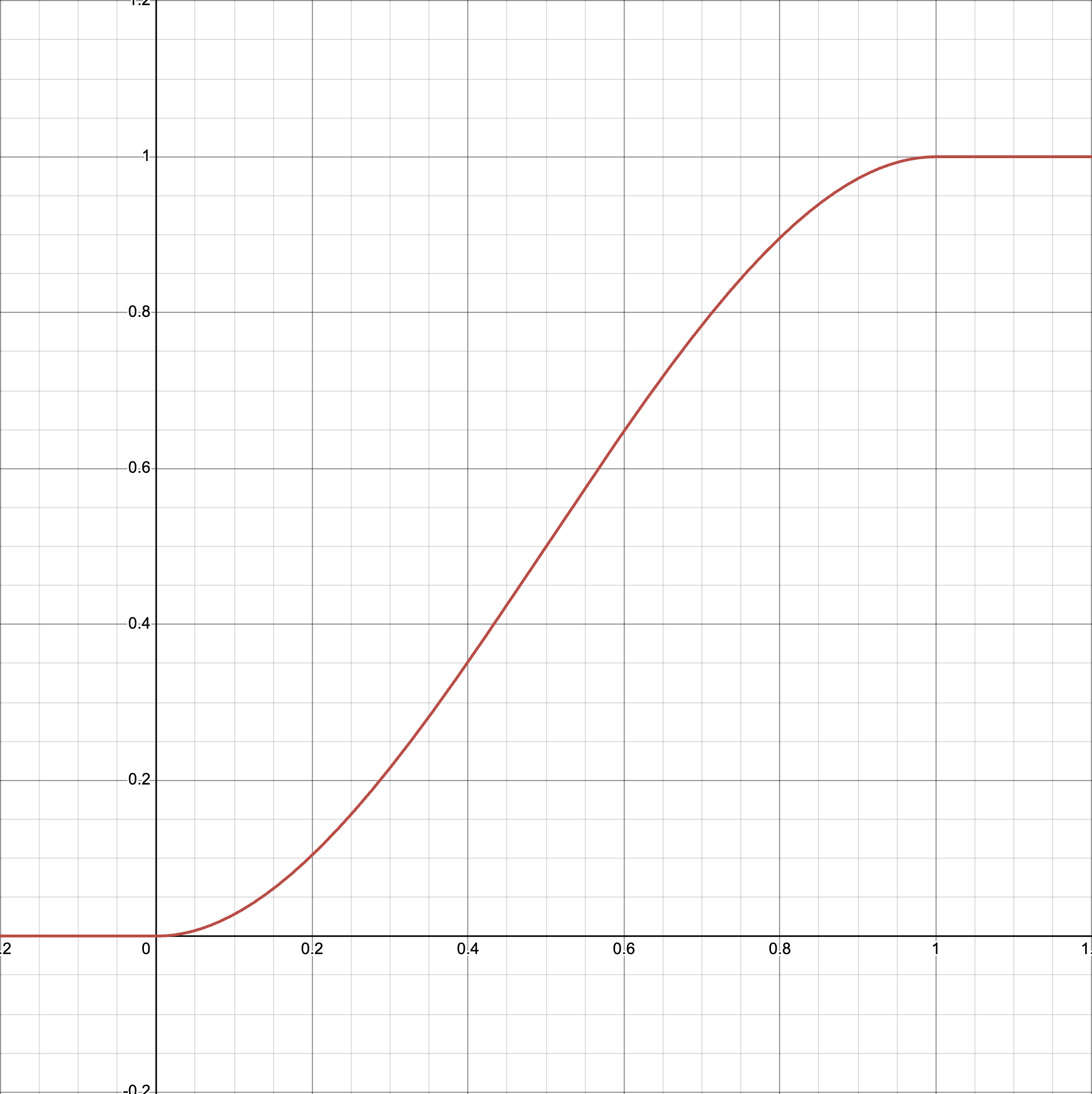
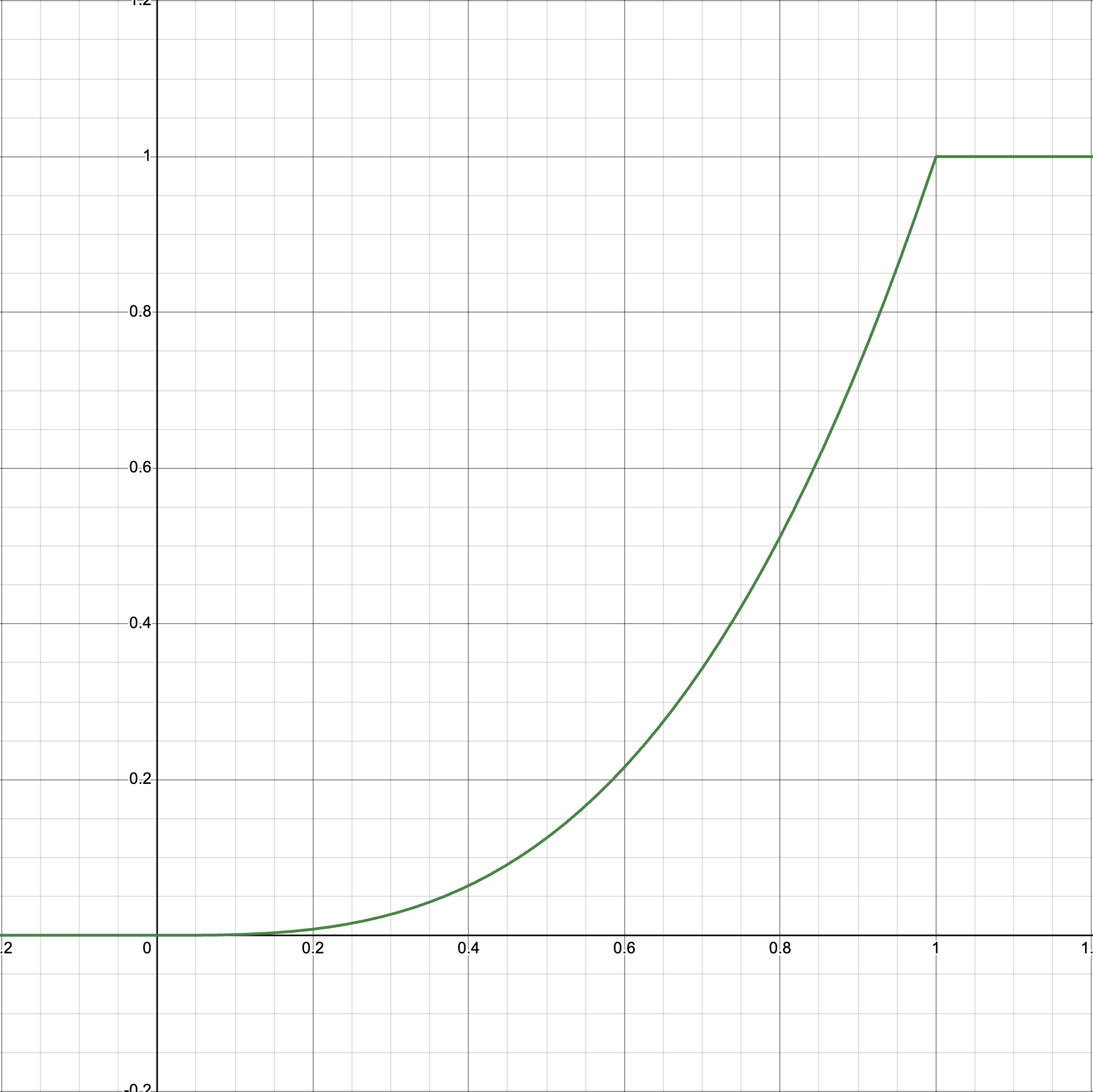
Exponential interpolation looks different — it has a smoother start and then drops off sharply at the end (or the opposite, if the exponent is less than 1). When we apply it to alpha, we get a different kind of fade gradient. Here’s what the graph looks like with an exponent of 3:
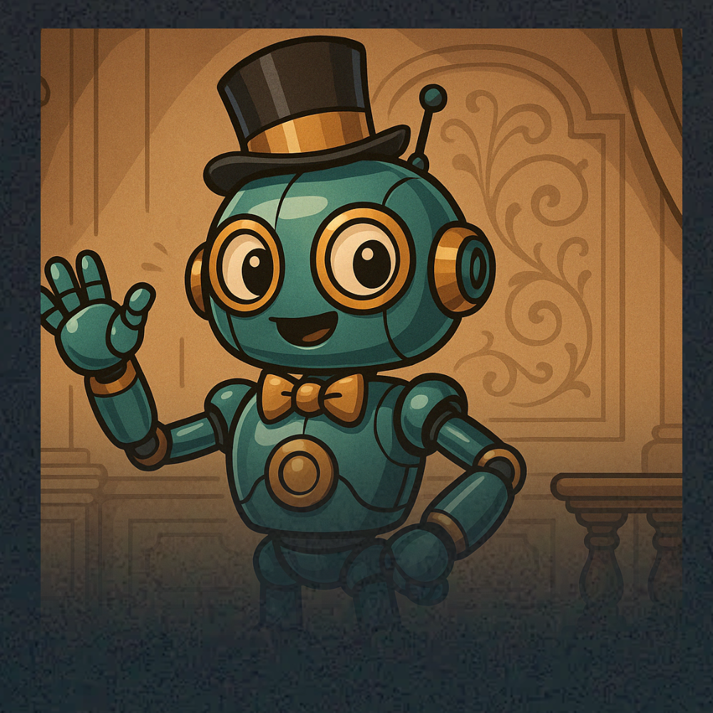
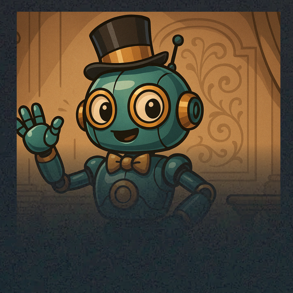
To make the difference clearer, below are two images. In both, alpha is applied from the center to the bottom edge — in the first one using smoothstep, and in the second one using exponential interpolation with an exponent of 3.
Smoothstep | Exponential (with pow 3) |
So, we can interpolate like that with the following method:
float ExponentialStep(float edge0, float edge1, float x, float exponent) { |
Shader Code |
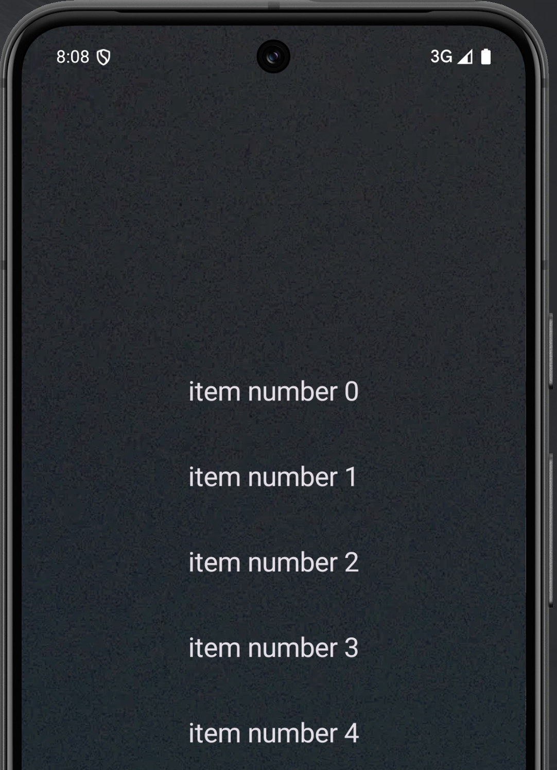
Let’s add a VerticalPager. Normally, I describe how to add Compose at the end of the chapter, since the main focus is on shaders. But for this effect, it’s better to set up Compose first so we can gradually walk through the shader part later.
So, our task in Compose is to add a VerticalPager and make sure the selected item is vertically centered. This behavior isn’t available out of the box, so we’ll need to get the height of the pager and the height of its item, then calculate the top padding. Here’s how to do it:
val pagerState = rememberPagerState(pageCount = { 30 })
| |
Compose Code | |
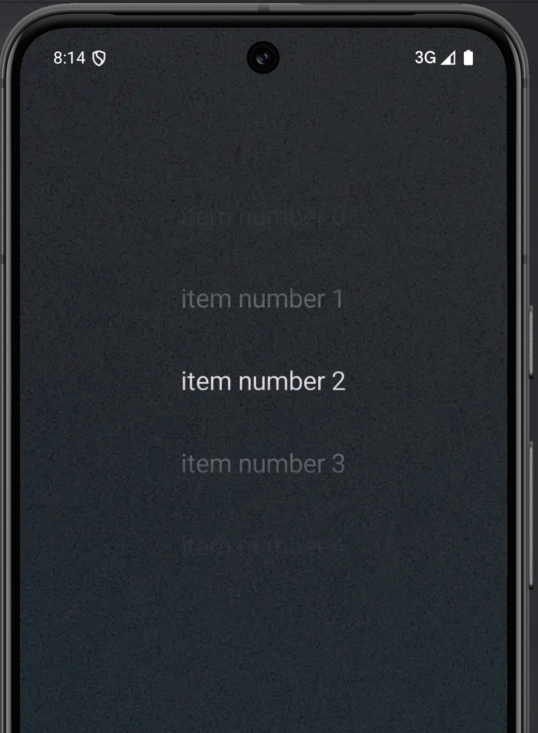
Now let’s wrap the pager in a box with a shader and get to the fun part! We’ll add vertical fading from the center using our exponential method.
vec4 main(float2 fragCoord) { vec4 content = GetImageTexture(uv, vec2(0.5, 0.5), resolution); | |
Shader Code | Result |
As I mentioned, this effect is very easy to achieve using a shader. So let’s play around a bit and add some horizontal compression. For that, we’ll use the GetImageTexture method we already wrote. Until now, we’ve been passing in our normalized coordinates unchanged — but let’s try multiplying the x value by some constant.
float xDistort = 2.0; //for now just some constant |
Shader Code |
Play around with the xDistort value and see how it affects the image. This is really important — we already used coordinate distortion in the previous chapter, but I always encourage experimenting with parameters as much as possible to start understanding and feeling them.
Now let’s think: what exactly do we want to achieve? We want the distortion not to be constant across the entire screen, but to increase as we move away from the vertical center. I’ll temporarily replace our pager with a square grid to make the deformation more visible
// rest of code | |
Shader Code | Result |
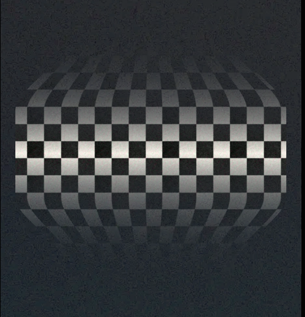
So, using the familiar smoothstep function, we adjust our scale factor based on the distance from the center. But then we add a strange-looking formula: (1.0 - xScale) + 1.0. Why do we need that? Because the ‘neutral’ state for our distortion is 1 — when we multiply the coordinates by vec2(1.0, 1.0), there’s no distortion at all. That happens when scaleX equals 1 (i.e., near the center, since 1.0 - 1.0 + 1.0 = 1.0). As we move away from the center, scaleX decreases, and the resulting factor grows — 1.1, 1.2, and so on.
Just for fun, try removing this adjustment entirely. That way, you’ll be changing the scale from 0 to 1 instead — and trust me, the result might surprise you. I’m not going to show it here — I’ll leave that discovery to you!
A sharp-eyed reader might ask: why did we go back to smoothstep instead of using our new ExponentialStep? The issue is that if you look closely at the graph, our exponential method has a sharp threshold at 1. That means the effect will have a noticeable jump from normal to distorted. You can still use it if you want — or even invert the function. Experiment and see what happens. Here, I used smoothstep again simply because it gives us a smoother transition without any visible break. |
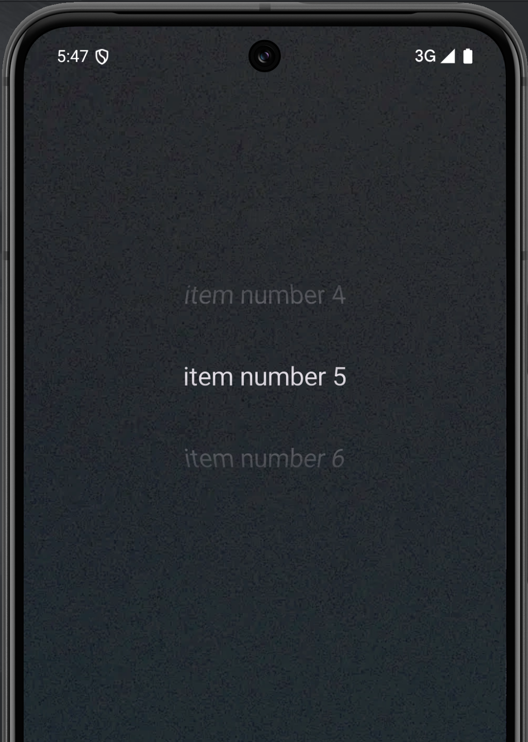
So, here’s the final shader code and the resulting effect:
uniform shader image; | |
Shader Code | Result |