In chapter 10, each matrix column told us where one axis step went. A rotation makes a particular choice: both steps keep length one, and their right angle stays intact. We only change their orientation.
One point on a circle
Start at (1,0), one unit to the right of the origin. Move this point around a circle of radius one. Measure the angle from the positive X axis, with positive angles going counterclockwise in our Y-up coordinates.
The point's horizontal coordinate is called the cosine of the angle. Its vertical coordinate is the sine. Those names give us the first rotated axis:
vec2 axisX = vec2(cos(angle), sin(angle));At 0° the point is (1,0). At +90° it is (0,1); at 180° it is (-1,0). A negative quarter-turn gives (0,-1). Because the point stays on the unit circle, cos(angle)² + sin(angle)² = 1.
GLSL's trigonometric functions take radians. One radian is the angle that cuts off an arc as long as the circle's radius. A full turn is 2π radians, a half-turn is π, and a quarter-turn is π/2. Convert degrees using degrees * π / 180; GLSL also has radians(degrees).
Our controls show degrees, but the host converts them once before sending uAngle. The shader receives radians already. Applying radians(uAngle) again would make a quarter-turn much too small.
Turn the second axis
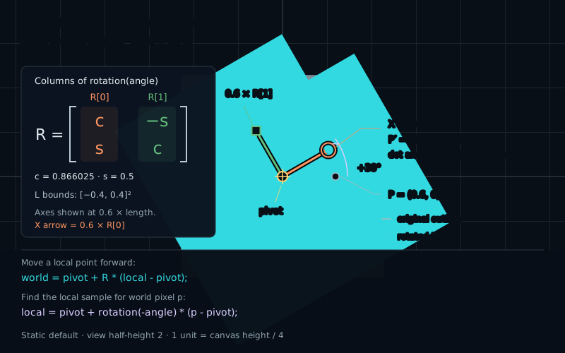
The Y axis starts a quarter-turn ahead of X. It must keep that relationship. For a vector (c,s), the perpendicular vector on its counterclockwise side is (-s,c). Put these two vectors into the columns:
mat2 rotation(float angle) {
    float c = cos(angle);
    float s = sin(angle);
    return mat2(c, s, -s, c);
}
The arguments still run down columns: (c,s), then (-s,c). At +90°, these become (0,1) and (-1,0). The original X step points up, and the original Y step points left. Both turned counterclockwise.
vec2 local = vec2(0.6, 0.0);
vec2 world = rotation(angle) * local;
// +90 degrees: world is approximately (0.0, 0.6).
// -90 degrees: world is approximately (0.0, -0.6).
A useful first test is a point on the positive X axis. If it goes down for a positive quarter-turn, inspect the signs and constructor order before changing the rest of the shader.
Why the shape stays rigid
Both columns have squared length c*c + s*s = 1. Their dot product is c*(-s) + s*c = 0, so they stay perpendicular. The matrix turns our coordinate frame without stretching or shearing it.
For any vector (x,y), the output is (cx−sy, sx+cy). Square both components and add: the cross terms cancel, leaving (c*c+s*s)*(x*x+y*y). This is the original squared length. The same cancellation preserves dot products between two transformed vectors, so angles between nonzero vectors stay the same.
For a shape, apply that reasoning to the displacement between any two of its points. Distances remain unchanged, including when we later choose an external pivot. Floating-point sine, cosine, and arithmetic introduce small errors; the laboratory readouts are approximate checks, not exact proofs.
Choose the pivot
Multiplication by R alone keeps the origin fixed. To rotate around another point, first measure a displacement from that point, rotate the displacement, then restore the point's position:
mat2 R = rotation(angle);
vec2 world = pivot + R * (local - pivot);
local is a point in the original, unrotated drawing. pivot uses that same coordinate frame and the same world-unit scale. Here these frames coincide before the transformation. The subtraction makes the pivot our temporary origin; the addition returns to the shared frame.
Substitute local=pivot: the displacement is zero, so the result is the pivot again. At angle zero, every point returns to itself. These two tests catch many mistakes in the order of the operations.
For P=(0.6,0), choose pivot=(0.8,0.4). The displacement is (-0.2,-0.4). A positive quarter-turn changes it to (0.4,-0.2); adding the pivot gives (1.2,0.2). The distance to the pivot stays √0.2, approximately 0.44721.
The icon's original origin O=(0,0) moves too: at that angle it reaches (1.2,-0.4). Its center travels around the pivot while its axes turn. Moving the center along a circle while keeping the icon upright would be a different motion. Watch both position and orientation to distinguish them.
Our L's origin is the center of its bounding square, not its area centroid. The extra subtraction and addition handle the pivot explicitly; they do not give mat2 a hidden translation component.
Ask where a pixel came from
The forward formula tells us where an original point goes. A fragment shader faces the opposite question. Its output pixel is already fixed at world position p. Which original point should supply its color?
Undo the turn. Subtract the same pivot, rotate by the negative angle, and add the pivot back:
vec2 local = uPivot + rotation(-uAngle) * (p - uPivot);
float d = iconDistance(local);
Turning by an angle and then by its opposite restores the original vector: rotation(-angle) * rotation(angle) is identity. This is the inverse for this particular transformation. We will develop general inverse matrices later.
At +90° around the origin, P=(0.6,0) moves to world (0,0.6). The pixel there applies −90° and recovers (0.6,0). It can now evaluate the original drawing. If we use +90° for this lookup instead, the rendered icon turns the other way.
Keep the two jobs separate in your reasoning: forward mapping moves a point; backward sampling finds the original coordinate for an output pixel. The opposite signs describe the same visible turn. The lab's axes and cyan marker use forward mapping, while the filled icon uses backward sampling.