Linear Algebra for GLSL Shaders
14 / Transform the space

Find the
way back.

A matrix tells us where a point goes. A fragment shader asks a different question: which original point belongs at this pixel?

25–35 min with experimentsGLSL ES 3.00 / WebGL 2After chapters 10–13
What we want to make

A pattern that stays on its shape.

Follow a pixel back ↓

Put a checkerboard and a small gold dot inside a circle. Stretch, lean, turn, and move the whole drawing. The pattern should travel with the circle, and the dot should meet a marker calculated by moving its original position forward.

Forward mapping sends local point (0.4,0.3) to world point (0.2,0.7). Inverse mapping subtracts translation, undoes rotation and shear, then divides by scale to recover (0.4,0.3).
One drawing · two directions of travelMove points forward. Look up the original drawing backward.

In chapter 13, we reversed known steps by hand. Now we will express the return trip with an inverse matrix. Keep the same column-vector convention and the distinction between local drawing coordinates and world coordinates.

Start with a fixed pixel

Imagine a local circle of radius 0.6. With uniform scale 2, its visible world radius should be 1.2. A world pixel at p=(1,0.5) belongs to the original drawing at local=(0.5,0.25).

vec2 local = p / 2.0;
float field = length(local) - 0.6;

Dividing the lookup coordinate makes the visible shape bigger. Why? The boundary now satisfies length(p/2)=0.6, or length(p)=1.2. A pixel twice as far from the origin retrieves the same original coordinate.

Multiplying p by 2 instead makes the boundary satisfy length(p)=0.3. This is the common mistake: using a forward point transformation as a sampling transformation. The shader is evaluating the color of a pixel that already has a position; it is not moving that pixel.

Add a translation t and the forward rule becomes world=2*local+t. Recover local by subtracting t first, then dividing by 2. Subtracting t after division would treat a world-space offset as though it were already local.

Name the return map

For a reversible matrix M, its inverse undoes M. We write it mathematically as M⁻¹ and in GLSL as inverse(M). Their products in either order give the identity matrix I:

M⁻¹ * M = I
M * M⁻¹ = I

These are mathematical identities. They mean that applying an action and its inverse restores any input vector. For a transformed drawing with world-space translation t:

vec2 world = M * local + t;
vec2 recovered = inverse(M) * (world - t);

Translation remains separate from mat2 because mat2 alone leaves the origin fixed. The inverse acts on the displacement world-t, measured from the transformed origin. We will give translation a place inside a larger matrix later.

GLSL ES 3.00 provides inverse for square matrices. It cannot recover a coordinate that a transformation has destroyed. Our lab keeps scale factors in [0.5,2], shear in [-1,1], and all parameters finite. Each individual operation has a defined reverse, and these bounds avoid extreme stretching ratios. Zero scale and collapse belong to the next chapter.

Do not substitute transpose(M) for inverse(M) in general. Transposing scale=(2,1) leaves that diagonal matrix unchanged, while its inverse needs scale=(0.5,1). Rotation has a special transpose relationship; scale and shear require the actual inverse.

Undo the last action first

Build one fixed chain from familiar pieces. Scale with S, apply horizontal shear H, rotate with R, then add the translation:

mat2 S = mat2(scale.x, 0.0, 0.0, scale.y);
mat2 H = mat2(1.0, 0.0, shear, 1.0);
mat2 M = R * H * S;
vec2 world = M * local + t;

To return, subtract t, rotate backward, undo the shear, then divide by scale. The inverse of the product therefore has the reversed order S⁻¹*H⁻¹*R⁻¹.

For two reversible matrices, inverse(A*B)=inverse(B)*inverse(A). We can see why by letting the neighboring actions cancel:

B⁻¹ * A⁻¹ * (A * B * local)
= B⁻¹ * (A⁻¹ * A) * B * local
= B⁻¹ * B * local
= local

Regrouping is allowed; exchanging actions is not. Writing inverse(A)*inverse(B) would generally undo them in the wrong order.

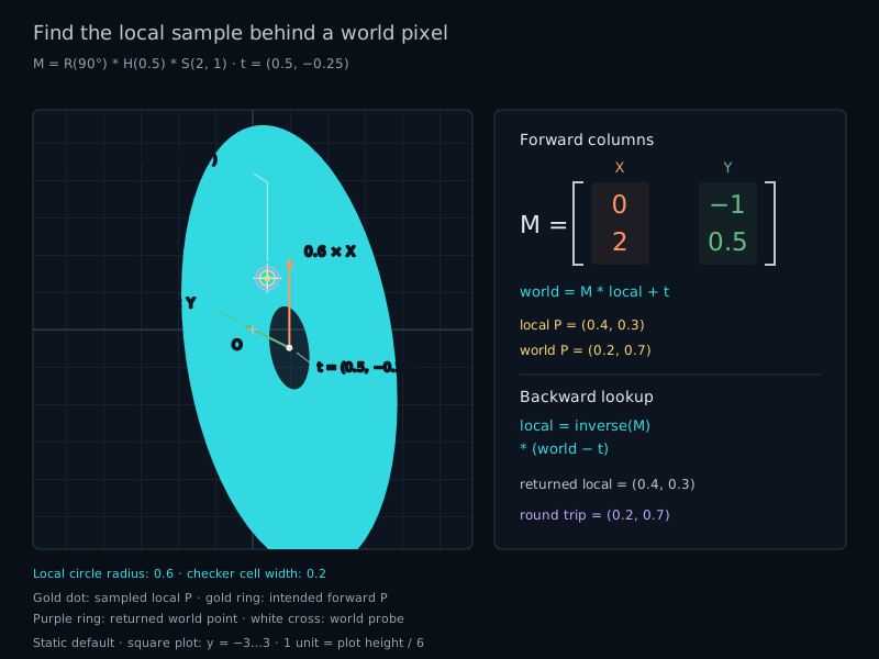
Use the Combined preset: 90°, scale=(2,1), shear=0.5, and t=(0.5,-0.25). P=(0.4,0.3) passes through (0.8,0.3), then (0.95,0.3), then (-0.3,0.95), and finally world=(0.2,0.7).

Follow the same numbers backward. Subtract t to get (-0.3,0.95). Rotate by -90° to recover (0.95,0.3). Subtract shear*y from X to recover (0.8,0.3). Divide by (2,1), and P returns.

Keep the pattern attached

A pattern stays attached when its colors and its shape mask use the same local coordinate. Our checkerboard uses squares 0.2 local units wide:

vec2 cell = floor(local / 0.2);
float checker = mod(cell.x + cell.y, 2.0);
float field = length(local) - 0.6;

floor selects an integer cell coordinate. The even or odd sum chooses one of two colors. This procedural pattern needs no image file. Its hard cell edges make the coordinate changes easy to inspect.

If you evaluate the checker with p while evaluating the mask with local, the figure moves across a pattern fixed in world space. Both choices can be useful, but only the shared local coordinate makes the pattern part of this drawing.

The small filled dot is also sampled in local space around P=(0.4,0.3). A separate gold ring uses the forward position M*P+t. With correct sampling, their centers agree as the controls change. This gives us a visible check that does not depend on the circle's symmetry.

Check the round trip

Move the white probe to a world position p. Recover its local coordinate, then send that coordinate forward again:

vec2 local = inverse(M) * (p - t);
vec2 roundTrip = M * local + t;
float error = length(roundTrip - p);

The returned point should meet the probe. Floating-point arithmetic leaves small numerical errors; it does not promise bit-for-bit identity. For this bounded lab, an error below 0.0001 world units is a useful reference check.

The Direct mistake mode deliberately uses M*(p-t) instead. At the Combined settings, the probe (0.2,0.7) retrieves (-0.95,-0.125). Sending that coordinate forward reaches (0.625,-2.2125), far from the probe.

The readouts are host float32 reference calculations, not GPU readback. They describe the built-in formulas even after shader edits. The probe may also be outside the figure: a valid lookup still exists there, but the mask returns background.

The circle field remains a local distance after deformation. Its sign and zero contour still define the mask; its magnitude is generally not a world-space distance. We use fwidth to smooth the rendered boundary approximately in screen space, as in chapter 12.

Try it

World → local → world.

LIVE GLSL / WEBGL 2

The transform order is fixed: scale, shear, rotate, translate. Compare Inverse with Direct mistake. Move the world probe, or use Probe marker to place it at the forward-mapped local dot.

The view stays fixed at −3 to 3 vertically, with equal X/Y units. One unit is one sixth of the canvas height. The axis guides are 0.6 times the full matrix columns, anchored at the translated origin; the column readouts show their unshortened values.

Static Combined setup: rotate 90 degrees, scale (2,1), shear 0.5, then translate by (0.5,-0.25). Local marker (0.4,0.3) appears at world (0.2,0.7), and inverse lookup recovers (0.4,0.3).
Checker: sampled local circlePale outline: intended forward circleGold dot: sampled local PGold ring: intended forward PWhite cross: world probePurple ring: returned pointOrange: 0.6 × first columnGreen: 0.6 × second column

Fixed view half-height 3: y runs from −3 to 3, with equal X/Y units. One unit is one sixth of the canvas height. Guide arrows start at translation and show 0.6 times each column; the numerical columns retain their full lengths. The intended circle outline uses 64 forward-mapped segments.

Find the local coordinate

Rotation, scale, and shear
Translation
World probe
Presets and control details

Combined restores the illustrated transform and probe. Identity sets M to identity, translation to zero, and probe to (0.4,0.3). Double size sets scale=(2,2), no rotation, shear, or translation, and probe=(1,0.5). Translate only sets M to identity, translation=(0.6,−0.3), and probe=(1,0.2).

These four presets select the correct Inverse mode and preserve the overlays. Probe marker moves only the probe to M*(0.4,0.3)+t. Ordinary parameter edits preserve the selected lookup mode.

Positive scales stay between 0.5 and 2, so all allowed transforms have an inverse. Reset lab restores Combined, Inverse, and both overlays; Reset code restores the shader separately.

Preparing the live shader.

World probe · p
(0.20000, 0.70000)
Correct lookup · inverse(M)*(p−t)
(0.40000, 0.30000)
Local coordinate used by selected mode
(0.40000, 0.30000)
Return point · M*usedLocal+t
(0.20000, 0.70000)
Selected lookup round-trip error
0.00000
Correct lookup round-trip error
0.00000
M[0] · full first column
(0.00000, 2.00000)
M[1] · full second column
(-1.00000, 0.50000)
inverse(M)[0]
(0.25000, -1.00000)
inverse(M)[1]
(0.50000, 0.00000)
Intended marker · M*(0.4,0.3)+t
(0.20000, 0.70000)
Selected lookup at the intended marker
(0.40000, 0.30000)

The correct lookup recovers the local point; sending it forward returns to the world probe. The gold sampled dot and intended forward ring align.

The view remains fixed. Returned points can leave the view in Direct mode; their numbers remain available below.

These numbers are host float32 references for the built-in formulas, not GPU measurements. Shader edits do not change them. Trigonometric functions, inverse arithmetic, and rounding can differ slightly on the GPU. The correct round-trip error is usually small rather than exactly zero. The sampled gold dot always represents local P=(0.4,0.3); its world position changes with the lookup.

The circle has local radius 0.6 and checker cells have local width 0.2. The mask and dot use fwidth for approximate screen antialiasing of local fields, which are not exact world distances. The checker uses hard floor boundaries and may alias at small sizes. Drawing helpers and colors are supplied.

Drag with a mouse to move the world probe, or focus the canvas and use arrow keys: 0.05 units per press, or 0.25 with Shift. On touch screens, a tap places the probe; swipes scroll the page normally. Probe coordinates stay within [−3,3]. Sliders and number fields also support the keyboard.

Open the complete shader edit · run · reset

The host supplies radians in uAngle, positive uScale, uShear, uTranslation, uProbe, and the lookup/overlay flags. M=R*H*S applies scale, then shear, then rotation; translation is added afterward. One selected local coordinate feeds the mask, checker, and dot. The forward guides keep their intended positions.

⌘ / Ctrl + Enter to run

The host code supplies bounded parameters and handles the editor and probe. Degrees are converted to radians once. The shader evaluates the mask, pattern, and sampled dot from the same lookup coordinate.

A complete inverse-sampling shader

Paste this smaller shader into the editor. It keeps the checker, sampled dot, forward gold ring, white probe, and purple return ring. The longer default shader adds axes, grid lines, and the intended shape outline.

#version 300 es
precision highp float;
uniform vec2 uResolution;
uniform float uAngle; // Radians, in [-pi, pi].
uniform vec2 uScale; // Both factors in [0.5, 2].
uniform float uShear; // In [-1, 1].
uniform vec2 uTranslation; // World units; each component in [-1, 1].
uniform vec2 uProbe; // World units; each component in [-3, 3].
uniform bool uDirectMistake;
out vec4 fragColor;

mat2 rotation(float angle) {
    float c = cos(angle), s = sin(angle);
    return mat2(c, s, -s, c);
}
void main() {
    vec2 p = 3.0 * (2.0 * gl_FragCoord.xy - uResolution) / uResolution.y;
    mat2 R = rotation(uAngle);
    mat2 H = mat2(1.0, 0.0, uShear, 1.0);
    mat2 S = mat2(uScale.x, 0.0, 0.0, uScale.y);
    mat2 M = R * H * S;
    // Positive bounded scales make this inverse well-defined here.
    mat2 lookup = uDirectMistake ? M : inverse(M);
    vec2 local = lookup * (p - uTranslation);
    float field = length(local) - 0.6;
    float dotField = length(local - vec2(0.4, 0.3)) - 0.035;
    // Derivatives are evaluated before any pixel-dependent selection.
    float edge = max(fwidth(field), 0.00001);
    float dotEdge = max(fwidth(dotField), 0.00001);
    float mask = 1.0 - smoothstep(-edge, edge, field);
    vec2 cell = floor(local / 0.2);
    float checker = mod(cell.x + cell.y, 2.0);
    vec3 ink = mix(vec3(0.09, 0.24, 0.29), vec3(0.24, 0.66, 0.72), checker);
    vec3 color = mix(vec3(0.04, 0.06, 0.09), ink, mask);
    float dotMask = 1.0 - smoothstep(-dotEdge, dotEdge, dotField);
    vec3 gold = vec3(1.0, 0.81, 0.31);
    color = mix(color, gold, dotMask * mask);

    float pixel = 6.0 / uResolution.y;
    vec2 markerWorld = M * vec2(0.4, 0.3) + uTranslation;
    float markerRing = 1.0 - smoothstep(pixel, 2.0 * pixel,
        abs(length(p - markerWorld) - 0.07));
    color = mix(color, gold, markerRing);
    vec2 sampledProbe = lookup * (uProbe - uTranslation);
    vec2 roundTrip = M * sampledProbe + uTranslation;
    float returnRing = 1.0 - smoothstep(pixel, 2.0 * pixel,
        abs(length(p - roundTrip) - 0.1));
    color = mix(color, vec3(0.77, 0.62, 1.0), returnRing);
    vec2 d = abs(p - uProbe);
    float crossField = min(max(d.x - 0.07, d.y - 0.008),
                           max(d.x - 0.008, d.y - 0.07));
    color = mix(color, vec3(0.95), 1.0 - smoothstep(0.0, pixel, crossField));
    fragColor = vec4(color, 1.0);
}

Your turn

Use Reset lab and Reset code first.

  1. At Combined, follow the probe (0.2,0.7) backward through translation, rotation, shear, and scale. Predict local before checking the readout. Then send it forward and compare with the probe.
  2. Choose Double size. Predict the visible circle radius and checker cell width in Inverse mode. Switch to Direct mistake and predict them again. Explain why dividing the lookup by 2 enlarges the image.
  3. Return to Combined and Inverse. Change all four kinds of transformation, then use Probe marker. Check that local returns to (0.4,0.3), that the dot and gold ring share a center, and that the round-trip error stays small.
  4. Paste the smaller shader. Replace only floor(local / 0.2) with floor(p / 0.2). Change translation and rotation. Explain why the pattern now slides across the figure, then restore local coordinates.
A hint

Undo the last action first. For the checker, ask whether each cell is addressed relative to the drawing or relative to the world. The correct gold marker position is always M*P+t.

Check your result

Combined recovers local=(0.4,0.3), and the correct round trip returns (0.2,0.7). Direct mistake instead returns (0.625,-2.2125), with error about 2.94335. Its sampled dot appears near (0.75,-0.65), away from the intended forward marker.

Double size gives radius 1.2 and world checker width 0.4 in Inverse mode; Direct mistake gives radius 0.3 and width 0.1. Identity and Translate only cannot expose this particular matrix mistake because M=I in both presets. A world-space checker remains fixed while the mask moves; using local for both restores attachment.

What you can do now

Recover a drawing's local coordinate from a world pixel and verify the return trip. Keep mask and pattern in the same space, explain the reversed order of inverse composition, and recognize a forward matrix used in the wrong direction. Next, we will examine transformations that flip or collapse space.