Linear Algebra for GLSL Shaders
13 / Transform the space

The order changes
the result.

Stretch a card, then turn it. Now turn the same card before stretching it. The numbers stayed the same. Why did the picture change?

25–35 min with experimentsGLSL ES 3.00 / WebGL 2After chapters 11–12
What we want to make

Two orders. Two different cards.

Compare the steps ↓

Use a 45° turn and double the horizontal coordinate. One order produces a rotated rectangle. The other produces a parallelogram with slanted corners. We will predict both by following a point and two axes through the steps.

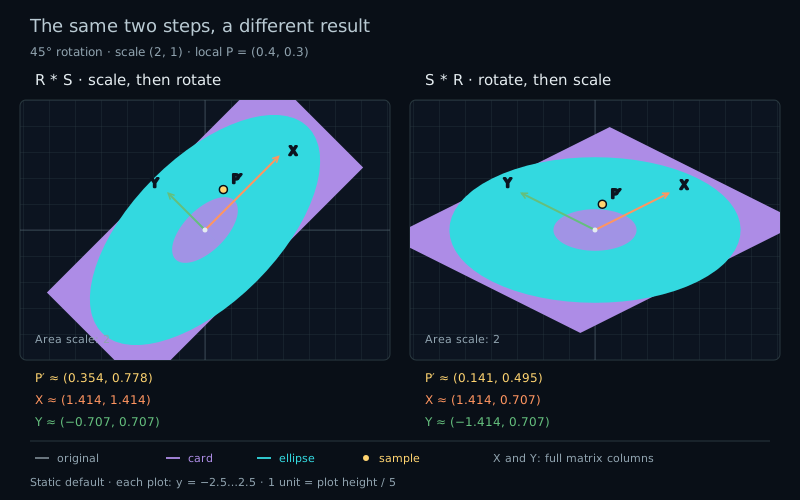
Two orders at 45 degrees and scale (2,1). R times S produces a rotated rectangle with perpendicular columns. S times R produces an oblique parallelogram. The same point (0.4,0.3) reaches (0.35355,0.77782) and (0.14142,0.49497).
Follow the first action · then the secondR * S and S * R use the same matrices in different orders.

We already have rotation and scale. This chapter adds no new kind of transform. It connects two familiar ones. Both act around the origin, and all vectors remain column vectors.

Follow one point

Keep the card from chapter 12: width 1.2, height 0.8, centered at the origin. Keep its circle of radius 0.5 and the marked point P=(0.4,0.3). Let S double X and leave Y alone. Let R rotate counterclockwise by 45°.

vec2 intermediate = S * local;
vec2 world = R * intermediate;

First, P becomes (0.8,0.3). Then the rotation mixes those two coordinates. At 45°, sine and cosine are both approximately 0.707107, giving world≈(0.35355,0.77782).

Now reverse the actions. Rotation first gives approximately (0.07071,0.49497). Doubling this result's X coordinate gives (0.14142,0.49497). The two paths reach different points because scale receives different inputs.

vec2 intermediate = R * local;
vec2 world = S * intermediate;

Notice what the second scale means. It stretches along the fixed world X and Y directions. After a turn, those directions no longer match the card's edges. Stretching them can change the angle between those edges.

Put the steps together

Substitute the first assignment into the second. The parentheses show the action closest to local happening first:

vec2 scaleThenRotate = R * (S * local);
vec2 rotateThenScale = S * (R * local);

We can store the combined action in one matrix:

mat2 combined = R * S;
vec2 world = combined * local;

Matrix multiplication is associative: mathematically, (R*S)*local equals R*(S*local). Regrouping keeps the order. Floating-point evaluation can produce small rounding differences, so compare computed values with a tolerance.

It is generally not commutative: exchanging R and S can change the result. Read R * S * local from the vector outward: scale, then rotate. The written matrix order describes a composition, not a left-to-right list of commands.

The same reasoning extends to three matrices: A * B * C * local applies C, then B, then A. Parentheses may group the work differently, but they do not permit exchanging the matrices.

Follow the columns

What does multiplying two matrices actually build? Each column of the right-hand matrix is a vector. Apply the left-hand matrix to each one:

mat2 combined = mat2(R * S[0], R * S[1]);
// The same column construction as R * S.

Write c=cos(angle) and s=sin(angle). Scale's columns are (scaleX,0) and (0,scaleY). Turning them produces the columns (scaleX*c,scaleX*s) and (-scaleY*s,scaleY*c). This is R*S.

At our settings, they are approximately (1.41421,1.41421) and (-0.70711,0.70711). Their lengths are 2 and 1, and their dot product is zero. Scale first stretches the card along its original edges; rotation then turns that rectangle without changing its right angles.

For S*R, start with rotation's columns (c,s) and (-s,c), then scale their components. The results are (scaleX*c,scaleY*s) and (-scaleX*s,scaleY*c). At 45° and (2,1), both have length about 1.58114, and their dot product is -1.5. They are not perpendicular.

The lab draws these full columns as orange X and green Y arrows. At step 1, they show only the first action. At step 2, they show the complete product. The intermediate overlay lets you keep the first step visible while inspecting the final one.

Both final cards have area 1.92: the original 0.96 multiplied by 2. Rotation preserves area, so placing it before or after this scale does not change that multiplier. Equal area does not imply equal shape.

The circle makes another difference visible. Scale first creates an ellipse with semiaxes 1 and 0.5, then rotation tilts it. Rotation first leaves the original circle unchanged as a shape; the following scale creates an ellipse aligned with the world axes. Its marked point still records the rotation.

When do they agree?

Try uniform scale=(1.5,1.5). Multiplying both coordinates by the same factor before or after rotation gives the same final matrix. The intermediate pictures still differ, but the endpoints agree for every point.

A zero angle also makes the final orders agree. So does a half-turn: R=-I sends every vector to its negative, which commutes with this diagonal scale. In general, these particular R and S commute when sin(angle)×(scaleX-scaleY)=0. Compare their columns above to see which off-diagonal terms must match.

This is a statement about the complete maps. A single coincident point proves less: the origin stays fixed for both orders at every setting. A symmetric unmarked shape can also hide changes. Use the two columns and a marked point instead of relying on one outline.

Undo the displayed steps

Our arrows and marker move forward. The fragment shader still starts at a fixed world pixel p and recovers the original drawing coordinate. For scale then rotate, undo the last action first: rotate back, then divide by scale.

// Forward: R * S * local
vec2 localRS = (rotation(-angle) * p) / scale;

// Forward: S * R * local
vec2 localSR = rotation(-angle) * (p / scale);

Check the first expression by reading its parentheses: the inverse rotation acts on p before division. For the second, division happens first. Both scale factors stay in [0.2,2], so division is defined. We will generalize this reversal into inverse matrices in the next chapter.

The masks remain local fields after deformation. As in chapter 12, their zero contours define the shapes, while fwidth supplies approximate screen-space smoothing. These values are not exact world-space distances.

Try it

Same inputs. Follow both paths.

LIVE GLSL / WEBGL 2

Use steps 0, 1, and 2 to reveal the original drawing, the first action, and the final composition. Swap order exchanges the two panel positions; it does not change the parameters.

Each view stays fixed at −2.5 to 2.5 vertically. X and Y use equal units, and one unit occupies a fifth of the canvas height. The interface displays degrees; the host converts the angle to radians once for GLSL.

R * S

Scale, then rotate · both actions

Static default comparison at 45 degrees and scale (2,1). Scale then rotate moves P to (0.35355,0.77782); rotate then scale moves P to (0.14142,0.49497).

S * R

Rotate, then scale · both actions

Static default comparison at 45 degrees and scale (2,1). Scale then rotate moves P to (0.35355,0.77782); rotate then scale moves P to (0.14142,0.49497).
Cyan: circle, local radius 0.5Purple: card, local size 1.2 × 0.8Gold: P=(0.4,0.3)Orange: first columnGreen: second columnGray: original shapes

Both views have fixed half-height 2.5, with equal coordinate units: y runs from −2.5 to 2.5, and one unit is one fifth of each canvas height. The arrows show full matrix columns. The finite local grid covers [−1,1], every 0.5 units. The faint centered unit cell starts at [−0.5,0.5] on both axes.

Two orders, shared parameters

Displayed step

Exchange panel positions only.

Preset and overlay details

Default: 45°, scale=(2,1). Quarter turn: 90°, (2,1). Uniform: 45°, (1.5,1.5). Zero angle: 0°, (2,1). These presets select step 2 and keep the panel order and overlay choices.

Swap order exchanges the left and right comparisons only. It does not change any numbers or the displayed step. At step 2, the subdued colored intermediate overlay shows each first action; the bright outlines and full columns show the result.

Reset lab restores 45°, scale=(2,1), step 2, R*S on the left, and all overlays. Reset code restores the shader separately.

R * S · host reference

Displayed map
R * S
P after first action
—
P in the displayed step
—
Displayed first column · M[0]
—
Displayed second column · M[1]
—
Displayed column lengths
—
Displayed column dot product
—
|P|: original → first → displayed
—
Displayed unit-cell area
—
Displayed card area
—

S * R · host reference

Displayed map
S * R
P after first action
—
P in the displayed step
—
Displayed first column · M[0]
—
Displayed second column · M[1]
—
Displayed column lengths
—
Displayed column dot product
—
|P|: original → first → displayed
—
Displayed unit-cell area
—
Displayed card area
—
Angle sent to shader · radians
0.78540
Final R*S*P
(0.35355, 0.77782)
Final S*R*P
(0.14142, 0.49497)
Final point separation · |R*S*P − S*R*P|
0.35355

At step 2 the two cards have equal area, but their shapes and sample positions differ. Matrix multiplication records which action comes first.

The view stays fixed as the parameters change. Some finite grid corners can be clipped at larger scales.

Numbers are host float32 reference calculations for the built-in formulas, not GPU measurements. Shader edits do not change these readouts. Trigonometric results and rounding can differ slightly on the GPU. Each panel's columns, area, and last distance follow the displayed step; “after first action” and the final comparison remain explicit references. Areas describe the shapes themselves, not their axis-aligned bounding boxes.

The circle and fill masks use local fields with fwidth for approximate screen antialiasing; they are not exact world-space distance fields. Thin forward-mapped card outlines keep their screen width. Drawing helpers are supplied.

Focus either diagram: Left/Right changes the angle by 1° (Shift: 15°); keys 0, 1, and 2 select a step. Both panels update together. Sliders and number fields have their own keyboard controls. There is no drag handle or animation; touch swipes scroll normally.

Preparing both live shaders.

Open the complete shader edit · run · reset

One fragment shader runs in both panels. The host supplies uOrder separately (0: R*S, 1: S*R), while uAngle, uScale, uStep, and the four overlay flags are shared. Run checks every available WebGL context before replacing any working program. A restored context uses the last accepted source.

⌘ / Ctrl + Enter to run

The host code runs the same shader in both panels with different order uniforms. Its reference numbers describe the built-in transformations; editing the shader does not change those numbers.

A complete order comparison shader

Paste this smaller version into the shared editor. It supports both orders and all three steps. The default shader adds grid lines, axes, and intermediate guides.

#version 300 es
precision highp float;
uniform vec2 uResolution;
uniform vec2 uScale; // Each factor is in [0.2, 2].
uniform float uAngle; // Radians, in [-pi, pi].
uniform int uOrder; // 0 = R*S, 1 = S*R.
uniform int uStep; // 0 = original, 1 = first action, 2 = both.
out vec4 fragColor;

mat2 rotation(float angle) {
    float c = cos(angle), s = sin(angle);
    return mat2(c, s, -s, c);
}
float boxField(vec2 p) {
    vec2 q = abs(p) - vec2(0.6, 0.4);
    return length(max(q, 0.0)) + min(max(q.x, q.y), 0.0);
}
void main() {
    vec2 p = 2.5 * (2.0 * gl_FragCoord.xy - uResolution) / uResolution.y;
    mat2 R = rotation(uAngle);
    mat2 S = mat2(uScale.x, 0.0, 0.0, uScale.y);
    mat2 M = mat2(1.0);
    vec2 local = p;
    if (uStep == 1) {
        M = uOrder == 0 ? S : R;
        local = uOrder == 0 ? p / uScale : rotation(-uAngle) * p;
    } else if (uStep == 2) {
        if (uOrder == 0) {
            M = R * S;
            local = (rotation(-uAngle) * p) / uScale;
        } else {
            M = S * R;
            local = rotation(-uAngle) * (p / uScale);
        }
    }
    // Local fields: correct contours, not world-space distances.
    float circle = length(local) - 0.5;
    float card = boxField(local);
    float circleAA = max(fwidth(circle), 0.00001);
    float cardAA = max(fwidth(card), 0.00001);
    vec3 color = vec3(0.04, 0.06, 0.09);
    float fill = 1.0 - smoothstep(-circleAA, circleAA, circle);
    color = mix(color, vec3(0.24, 0.88, 0.94), 0.16 * fill);
    float cardLine = 1.0 - smoothstep(cardAA, 2.0 * cardAA, abs(card));
    color = mix(color, vec3(0.77, 0.62, 1.0), cardLine);
    float circleLine = 1.0 - smoothstep(circleAA, 2.0 * circleAA, abs(circle));
    color = mix(color, vec3(0.24, 0.88, 0.94), circleLine);
    vec2 sampleWorld = M * vec2(0.4, 0.3);
    float pixelSize = 5.0 / uResolution.y;
    float marker = 1.0 - smoothstep(0.035, 0.035 + pixelSize,
                                   length(p - sampleWorld));
    color = mix(color, vec3(1.0, 0.81, 0.31), marker);
    fragColor = vec4(color, 1.0);
}

Your turn

Use Reset lab and Reset code first.

  1. Select step 0, then sketch both final cards for 45° and scale=(2,1). Predict the intermediate and final positions of P. Predict first; then use step 1 to check the first action and step 2 to check your composition.
  2. Explain which final card keeps perpendicular edges. Compare the columns' dot products, then compare the two ellipses. Why does the second ellipse remain aligned with world axes?
  3. Find settings where the final maps agree. Try uniform scale, zero angle, and a half-turn. Return to scale=(2,1) and try +90°: predict both positions of P.
  4. Run the smaller shader at the default settings and step 2. Replace only M = R * S; with M = S * R;. Which marker moves, and why does its filled shape stay put? Restore the line so the forward marker and backward-sampled shape agree again.
A hint

At 45°, R maps (x,y) to approximately (0.707107×(x-y),0.707107×(x+y)). The gold marker uses M; the shapes use local. Changing one calculation does not automatically update the other.

Check your result

For R*S, P passes through (0.8,0.3) and ends near (0.35355,0.77782). For S*R, it passes through (0.07071,0.49497) and ends near (0.14142,0.49497). The column dot products are 0 and -1.5. Both final cards have area 1.92.

Uniform scale, zero angle, and a half-turn give matching final maps, within floating-point precision. At +90° with scale=(2,1), R*S gives P=(-0.3,0.8); S*R gives P=(-0.6,0.4). The code mistake moves only the R*S panel's marker to the other result while its mask keeps the original lookup. The marker leaves its intended circle boundary.

What you can do now

Read a matrix product by following its actions from the vector outward. Predict both orders, identify the first action, and use intermediate columns to explain the difference. Next, we will make the return trip from world coordinates to local coordinates explicit.