Linear Algebra for GLSL Shaders
05 / Meet the vectors

A straight line
between two ideas.

Move a marker between two points and blend its color along the way. One number controls both changes.

20–30 min with experimentsGLSL ES 3.00 / WebGL 2After chapters 02–04
What we want to make

A point partway to its target.

Move along the line ↓

At zero, the marker sits at A. At one, it reaches B. Between them, it follows a straight segment. Keep increasing the same number and it continues beyond B.

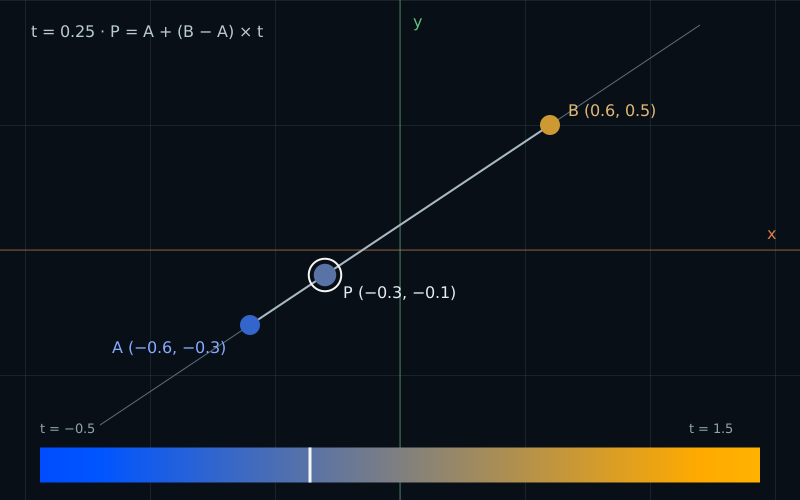
A marker at t=0.25 lies one quarter of the way from A at (-0.6,-0.3) to B at (0.6,0.5), at position (-0.3,-0.1).
Start + a fraction of the displacementA + (B − A) × 0.25 = (−0.3, −0.1)

Imagine moving an indicator from one button to another. We know where it starts and where it ends. What should its position be one quarter of the way through the move?

We can answer with the displacement from chapter 02. First find the change needed to reach the target. Then take only part of that change.

Take part of a displacement

Use two points in our equal-unit coordinate space. Both components have the same scale; positive Y points up.

vec2 a = vec2(-0.6, -0.3);
vec2 b = vec2( 0.6,  0.5);
vec2 displacement = b - a; // (1.2, 0.8)

The displacement says “move 1.2 right and 0.8 up.” A quarter of it is (0.3, 0.2). Add that smaller displacement to A:

float t = 0.25;
vec2 position = a + (b - a) * t;
// (-0.6, -0.3) + (0.3, 0.2) = (-0.3, -0.1)

t is a dimensionless fraction, not a distance. With t = 0, we add no displacement. With t = 1, we add the whole displacement and reach B. Halfway means t = 0.5, regardless of how far apart A and B are.

The same scalar multiplies both components. We take the same fraction of the horizontal and vertical change. This is what keeps the point on the straight line through A and B.

Do we need normalize(b - a) from the previous chapter? No. That would discard the distance between the endpoints. At t = 1, adding a unit direction would move only one unit from A. Here we need the original displacement to reach B exactly.

Write it with two weights

Expand the same expression and group the contributions from the endpoints:

a + (b - a) * t
= a + b * t - a * t
= a * (1.0 - t) + b * t

The two weights are 1 - t and t. They always add to one. At a quarter of the journey, the result is 0.75 * a + 0.25 * b. At the midpoint, both weights are 0.5.

We are taking a weighted combination of point coordinates in the same space. This differs from simply adding two positions: the weights preserve the common coordinate origin. Shifting both endpoints by the same amount shifts the result by that amount too.

GLSL gives this operation a name you may remember from the first book:

vec2 position = mix(a, b, t);

For these floating-point inputs, mix evaluates the weighted blend. Finding a value between two endpoints this way is linear interpolation. The two formulas are mathematically equivalent. Different evaluation orders can introduce tiny floating-point differences, so compare their results with a small tolerance rather than requiring every last bit to match.

Go beyond the endpoints

Nothing in the formula stops at B. At t = 1.5, we take one and a half displacements:

vec2 position = a + vec2(1.2, 0.8) * 1.5;
// (-0.6, -0.3) + (1.8, 1.2) = (1.2, 0.9)

Estimating a value beyond the endpoint interval is extrapolation. A negative t goes behind A; for example, t = -0.5 gives (-1.2, -0.7). In the weighted form, one weight is now negative.

mix does not clamp its parameter. If an indicator must stay inside its segment, make that rule explicit:

vec2 position = mix(a, b, clamp(t, 0.0, 1.0));

Our playground leaves t unclamped within its control range, -0.5 to 1.5, so you can see both behaviors. If A and B coincide, their displacement is zero and the result stays at A for every value of t. No normalization or division is involved.

Try it

One parameter. Two endpoints.

LIVE GLSL / WEBGL 2

Move Manual t first. The marker shows the position; the color strip shows the blend over the full parameter range. Choose an endpoint to move, or enter its coordinates. Y runs from -1 to 1 with no extra zoom.

The timeline controls below are a second way to choose t. They start paused. Readouts evaluate the built-in formulas on the host; they do not measure arbitrary code you put in the shader editor.

Static default example: A is (-0.6,-0.3), B is (0.6,0.5), and t is 0.25. Both interpolation formulas place P at (-0.3,-0.1). The mixed RGB color is (0.35,0.45,0.65).
Blue: AGold: BColored dot / white ring: both P formulas

Equal units; no extra zoom. Vertical range: −1 to 1. Grid: 0.5 units.

The shader's color strip runs from t = −0.5 on the left to t = 1.5 on the right. Its white mark shows the current t. The marker and strip clamp mixed RGB to 0–1 before blending their soft edges.

A · (0.2, 0.4, 0.8)
Displayed RGB(t)
B · (0.8, 0.6, 0.2)

Manual parameter

Manual t goes straight to the shader. Changing it pauses playback and detaches the timeline.

Optional timeline

Manual t controls the preview. The timeline is detached.

Paused. Play starts a fresh four-second pass from A to B.

Changing s or Mapping pauses playback and uses the timeline to compute t immediately. Playback stops at B, when the preview leaves view, or when the page is hidden. Reduced motion keeps playback off; the slider still works.

Endpoint A
Endpoint B
Move in the diagram:

Preparing the live shader.

Parameter sent to shader · t
0.25000
Timeline progress · s
0.25000 · detached
Displacement · B − A
(1.20000, 0.80000)
P · A + (B − A) × t
(−0.30000, −0.10000)
Same P · mix(A, B, t)
(−0.30000, −0.10000)
Max component difference · reference
0.00e+0
Raw RGB · mix(colorA, colorB, t)
(0.35000, 0.45000, 0.65000)
Displayed RGB · clamped to 0–1
(0.35000, 0.45000, 0.65000)

t is between 0 and 1, so P lies on the segment from A to B.

Position readouts are JavaScript float32 reference calculations, with a tolerance of 0.000001 for the largest component difference. The GPU may round the last digits differently. Readouts and HTML swatches follow the built-in formulas, not your shader edits. Raw RGB is shown before display clamping.

Select A or B, then click or drag in the diagram. Clicking near either endpoint selects it. Focus the diagram and use arrow keys for steps of 0.05; hold Shift for 0.25. A touch tap moves the selected endpoint; a swipe scrolls the page. Endpoint coordinates range from −1 to 1. Extrapolation may put P outside the visible area.

Open the complete shader edit · run · reset

The page supplies uA, uB, uT, and uResolution. JavaScript maps timeline progress s to t before sending uT; this shader applies no easing. The color strip shows t from −0.5 to 1.5. Drawing helpers are supplied geometry; the interpolation formulas in main() are the lesson.

⌘ / Ctrl + Enter to run

The complete editor includes supplied grid, segment, and marker drawing helpers. The position and color calculations are the lesson. The host code sends the endpoints and current parameter to the shader.

Use the same idea for color

A color has three components instead of two. The operation stays the same:

vec3 colorA = vec3(0.2, 0.4, 0.8);
vec3 colorB = vec3(0.8, 0.6, 0.2);
vec3 color = mix(colorA, colorB, t);
// (0.2 + 0.6*t, 0.4 + 0.2*t, 0.8 - 0.6*t)

At t = 0.25, the color is (0.35, 0.45, 0.65). At t = 0.5, it is (0.5, 0.5, 0.5). The marker uses the same parameter for its position and color, so both arrive at their endpoints together.

Extrapolated color values can leave the usual display range. At t = 1.5, the raw result is (1.1, 0.7, -0.1). This demo explicitly clamps the displayed color to (1.0, 0.7, 0.0), while keeping the raw value in the readout. Clipping the display does not change the interpolation formula.

A complete moving marker

Paste this smaller fragment shader into the editor. The endpoint, parameter, and timeline controls still work. Each pixel measures its distance from the interpolated position, using the circle technique from chapter 03.

#version 300 es
precision highp float;
uniform vec2 uResolution;
uniform vec2 uA;
uniform vec2 uB;
uniform float uT;
out vec4 fragColor;

void main() {
    vec2 p = (2.0 * gl_FragCoord.xy - uResolution) / uResolution.y;
    vec2 position = mix(uA, uB, uT);
    vec3 color = mix(vec3(0.2, 0.4, 0.8),
                     vec3(0.8, 0.6, 0.2), uT);
    float marker = 1.0 - smoothstep(0.045, 0.055, length(p - position));
    vec3 background = vec3(0.04, 0.06, 0.09);
    fragColor = vec4(mix(background, clamp(color, 0.0, 1.0), marker), 1.0);
}

The first mix chooses a position, the second chooses its color, and the last draws that color over the background using a soft circular mask. The same operation works with a scalar, a vec2, or a vec3.

Separate path and timing

So far, we have chosen t by hand. For an animation, introduce s: elapsed time divided by the duration, clamped to 0–1. Our Play from A button runs one four-second pass.

float t = s; // Linear timing.
vec2 position = mix(a, b, t);

Equal time steps now give equal displacements. To start and finish more slowly, change how time produces the fraction:

float t = s * s * (3.0 - 2.0 * s); // Eased timing, s in [0, 1].
vec2 position = mix(a, b, t);

This is the polynomial used by smoothstep(0.0, 1.0, s). At s = 0.25, linear timing gives t = 0.25; eased timing gives t = 0.15625. The marker has covered less distance. At the midpoint both give t = 0.5.

Both components still use the same t, so the path stays straight. Easing changes the speed along that path. In this demo, JavaScript calculates the timing parameter and sends uT; the shader needs only the current fraction.

Try a mistake in the complete moving-marker shader: replace its position line with vec2 position = mix(uA, uB, vec2(uT, uT * uT));. Set Manual t to 0.5. X is halfway but Y is only a quarter of the way. With our endpoints, the marker moves to (0.0, -0.1), away from the straight segment. Different component fractions changed the path itself. Restore the original line afterward.

Your turn

Use Reset lab to restore the default endpoints and shader.

  1. Before touching the controls, predict the position at t = 0, 0.25, 1, and 1.5. Check each preset and compare both position formulas.
  2. At t = 1.5, predict the raw color and the displayed color. Explain why the marker goes beyond B even though the displayed channels stay between zero and one.
  3. Set timeline progress s to 0.25. Switch from Linear to Eased. Predict the new t and position. Try Play from A in both modes and compare the path.
  4. Use Set B = A. Change Manual t, including values outside 0–1. Explain why the position stays fixed while its color can still change.
A hint

The default displacement is (1.2, 0.8). Multiply it by t before adding A. For eased timing, calculate the new t first and use that same value in both position components.

Check your result

The positions are (-0.6, -0.3), (-0.3, -0.1), (0.6, 0.5), and (1.2, 0.9). The formulas agree within floating-point rounding.

At t = 1.5, raw RGB is (1.1, 0.7, -0.1); displayed RGB is (1.0, 0.7, 0.0). At s = 0.25, eased t is 0.15625 and position is (-0.4125, -0.175). Both timing modes follow the same straight segment. With A = B, the position cannot change because B − A is zero; the two color endpoints are still different.

What you can do now

You can predict a point between or beyond two endpoints, obtain it with either formula, and change its speed without bending its path. Next, we will measure how much one direction agrees with another and use that measurement to draw a directed gradient.