Linear Algebra for GLSL Shaders
06 / Make directions useful

How much do two
directions agree?

Turn a gradient in any direction with one formula. Measure how far each pixel lies along an arrow, then use that number to blend two colors.

20–30 min with experimentsGLSL ES 3.00 / WebGL 2After chapters 04–05
What we want to make

A gradient that follows an arrow.

Turn the gradient ↓

Point right for a left-to-right blend. Point upward for a bottom-to-top blend. A diagonal arrow gives a diagonal change, while points sideways from the arrow can share exactly the same color.

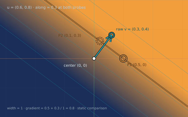
Unit direction (0.6,0.8) measures 0.3 along the direction at both probe (0.5,0) and probe (0.1,0.3). The line joining those probes is perpendicular to the direction.
Different positions. The same amount along the direction.dot((0.5, 0), (0.6, 0.8)) = 0.3

In chapter 05, one parameter blended two colors. Now each pixel needs its own parameter. Reading p.x gives a horizontal change, and reading p.y gives a vertical one. How do we read a coordinate along a diagonal?

We will combine the two components using a direction. Then turning that direction will turn the gradient, without changing the rest of the shader.

Multiply, then add

Start with two vectors. Multiply the matching components, then add the results:

vec2 d = vec2(0.5, 0.0);
vec2 u = vec2(0.6, 0.8);
float along = d.x * u.x + d.y * u.y;
// 0.5 * 0.6 + 0.0 * 0.8 = 0.3

This operation is the dot product. Its result is one number, a scalar. GLSL writes it as:

float along = dot(d, u);

Do not confuse it with d * u. Multiplying two vec2 values with * gives the component-wise pair (0.3, 0.0). The dot product adds that pair to get 0.3. In 3D, it adds the Z product as well.

Measure one direction

Let d be a displacement and u a unit direction. Then dot(d, u) measures how much of that displacement lies along u, including its sign.

For u = (1, 0), the formula returns d.x. For u = (0, 1), it returns d.y. A diagonal unit vector combines both components into a coordinate along that diagonal.

Why must the measuring direction have length one? Move exactly k units along it. The displacement is k * u:

dot(k * u, u)
= k * (u.x * u.x + u.y * u.y)
= k * 1.0
= k

The middle sum is one because u has length one. The measurement therefore returns the distance we traveled, with a negative value when we travel backward. This signed number is also called a scalar projection. It is not a position or a vector.

For our gradient, the displacement starts at a chosen center:

vec2 d = p - center;
float along = dot(d, unitDirection);

p and center use the equal-unit space from chapter 01. Their difference is in coordinate units. The unit direction is dimensionless, so along is also in coordinate units.

Read the sign

For two unit vectors, the result stays between -1 and 1. Compare these directions with u = (0.6, 0.8):

Dot products with the unit direction (0.6, 0.8)
Other unit vectorProducts and sumMeaning
(0.6, 0.8)0.36 + 0.64 = 1Same direction
(-0.8, 0.6)-0.48 + 0.48 = 0Perpendicular
(-0.6, -0.8)-0.36 - 0.64 = -1Opposite direction

A positive result means the vectors point partly toward the same side. A negative result means they point partly against each other. Zero means perpendicular when both vectors are nonzero. The zero vector also has dot product zero with everything, but it has no direction to compare.

For arbitrary vectors, the result also depends on their lengths. Doubling either input doubles the dot product; doubling both multiplies it by four. For example, dot((0.3, 0.4), (0.3, 0.4)) is 0.25, not one, even though the directions match perfectly.

In GLSL, dot(v, v) is the squared length of v. Normalize both inputs when you want a pure comparison of direction. In our gradient, normalize only the measuring arrow. Keep the pixel displacement’s length: that is the distance we want to measure.

Turn the number into color

At the center, along is zero. On the forward side it is positive; on the backward side it is negative. Map a band around zero into the 0–1 range needed by mix:

float gradient = clamp(0.5 + along / width, 0.0, 1.0);
vec3 color = mix(colorA, colorB, gradient);

width is the full transition width in coordinate units, measured along the unit direction. At along = -width / 2, the blend reaches zero. At the center it is 0.5. At along = width / 2, it reaches one. Beyond those boundaries, clamping keeps an endpoint color.

With width 1 and our probe at (0.5, 0), along = 0.3, so the blend is 0.8. Making the width smaller creates a sharper wipe. Moving the center slides the transition through the image.

Width must stay positive. This demo limits it to 0.02–2. A width of zero would introduce division by zero; use an explicit step for a truly hard boundary instead.

Try it

Turn the direction. Read the pixel.

LIVE GLSL / WEBGL 2

Drag the direction handle or enter its components. The raw arrow runs from the center to center + direction; the shader uses its normalized direction. Move the probe to inspect one pixel position. Equal-value lines show where along stays constant.

Y runs from -1 to 1 with no extra zoom. Readouts evaluate the built-in formulas on the host and do not inspect custom shader code. Try Double length: the raw arrow grows, but the gradient keeps its width.

Static default example: center (0,0), raw direction (0.3,0.4), unit direction (0.6,0.8), width 1. Probes at (0.5,0) and (0.1,0.3) both have along 0.3 and gradient 0.8; they lie on the same equal-value line.
White: centerCyan: raw direction arrow / handleAmber: probe / its equal-value line

Equal units; no extra zoom. Vertical range: −1 to 1. Grid: 0.5 units.

The direction handle is at center + raw direction. Its distance from the center changes the raw arrow's length. Normalization keeps that length out of the gradient formula. Cyan guide lines are 0.25 units apart in along; the amber line passes through the probe.

Direction and width

Raw direction v

Double and Half multiply both raw components by the same factor. Double is disabled if a component would exceed −1 to 1. A direction length at or below 0.0001 uses the fixed unit fallback (1,0).

Center
Probe

Both probe presets restore center (0,0), raw direction (0.3,0.4), and width 1. They place the probe at two different points with the same along value.

Preparing the live shader.

Raw direction length · length(v)
0.50000000
Unit direction · u
(0.60000, 0.80000)
Probe displacement · δ = probe − center
(0.50000, 0.00000)
Component products · (δ.x × u.x, δ.y × u.y)
(0.30000, 0.00000)
Sum of the two products
0.30000
Signed component · along = dot(δ, u)
0.30000
Gradient · clamp(0.5 + along / width, 0, 1)
0.80000
Comparison only · dot(δ, raw v)
0.15000

The raw direction is long enough to normalize. The gradient uses its unit direction.

The probe is on the positive side of the center's equal-value line. Moving it along the amber line leaves along unchanged.

Readouts are JavaScript float32 reference calculations of the built-in formulas. The GPU may round the last digits differently. Editing the shader does not change these readouts. The raw dot comparison shows the effect of the raw vector's length; the gradient always uses the unit direction.

Move with pointer or keyboard:

Selected: direction handle. Click or drag to move the selected item; clicking near a handle selects it. Focus the diagram and use arrow keys for steps of 0.05; hold Shift for 0.25. On a touch screen, tap a location or use the controls; a swipe scrolls the page. Moving the center also moves the raw direction handle.

Open the complete shader edit · run · reset

The page supplies uCenter, raw uDirection, uProbe, positive uWidth, uShowLines, and uResolution. The shader normalizes the raw direction with an explicit guard. Drawing helpers build the grid, arrow, and markers. The along and gradient calculation in main() is the lesson.

⌘ / Ctrl + Enter to run

The complete editor supplies drawing helpers for arrows, markers, and guide lines. The lesson is the calculation of along and gradient. The host code handles controls and sends uniforms. The scene renders when something changes.

A complete directional gradient

Paste this smaller shader into the editor. It draws only the gradient. The direction, center, and width controls still work.

#version 300 es
precision highp float;
uniform vec2 uResolution;
uniform vec2 uCenter;
uniform vec2 uDirection;
uniform float uWidth;
out vec4 fragColor;

void main() {
    vec2 p = (2.0 * gl_FragCoord.xy - uResolution) / uResolution.y;
    float len = length(uDirection);
    vec2 unitDirection = vec2(1.0, 0.0);
    if (len > 0.0001) {
        unitDirection = uDirection / len;
    }
    float along = dot(p - uCenter, unitDirection);
    float width = max(uWidth, 0.02);
    float gradient = clamp(0.5 + along / width, 0.0, 1.0);
    vec3 colorA = vec3(0.10, 0.18, 0.35);
    vec3 colorB = vec3(0.95, 0.62, 0.24);
    fragColor = vec4(mix(colorA, colorB, gradient), 1.0);
}

The direction guard repeats chapter 04: for a zero or very short input, we choose +X before any division. The threshold 0.0001 is a scene-specific tolerance in coordinate units. Below it, the fallback may change the gradient’s orientation. Ordinary positive changes of arrow length above the threshold leave its direction unchanged.

Move without changing color

Keep the default unit direction (0.6, 0.8). Probe 1 is at (0.5, 0). Probe 2 is at (0.1, 0.3). Their measurements are:

// Probe 1: 0.5 * 0.6 + 0.0 * 0.8 = 0.30
// Probe 2: 0.1 * 0.6 + 0.3 * 0.8 = 0.06 + 0.24 = 0.30

We moved by (-0.4, 0.3). Its dot product with the unit direction is -0.24 + 0.24 = 0, so this sideways displacement adds nothing to along. Both probes have blend value 0.8.

That is why the guide lines run perpendicular to the arrow. You can move anywhere along one of those lines without changing the measurement. Moving across the lines, along the arrow, changes it.

For any 2D direction u, the vector (-u.y, u.x) is perpendicular to it: their component products cancel. This gives us a useful way to check a sideways movement without calculating an angle.

A mistake worth making: keep the arrow’s length

In the smaller shader, replace dot(p - uCenter, unitDirection) with dot(p - uCenter, uDirection). At the default probe, the result becomes 0.15 and the blend becomes 0.65.

Use Double length. The measurement doubles and the transition becomes narrower. The shader is now measuring with a scaled direction, so its width setting no longer describes the visible width directly. Restore unitDirection to separate orientation from scale.

Normalizing p - uCenter instead would remove the distance from the center. Points at different distances along the same ray would then get the same measurement. Keep the displacement; normalize the measuring direction.

Your turn

Use Reset lab to restore the original shader and controls.

  1. Choose Right. Predict the orientation of the middle boundary, then try Up. Use Diagonal and Reverse to change orientation and swap the forward and backward colors without editing the formula.
  2. Restore Diagonal, center zero, and width 1. Compare the raw dot product and along before and after Double length. Predict which one changes.
  3. Choose Probe 1, then Probe 2. Both presets restore the default direction and width. Check the component products and explain why the sums match.
  4. Choose Narrow wipe and move the center. Then choose Zero vector. Explain why a valid gradient remains even though the raw arrow has no direction.
A hint

The arrow points across the transition. The middle boundary runs perpendicular to it. Normalize the arrow before measuring; a perpendicular displacement contributes zero.

Check your result

Right gives a vertical middle boundary; Up gives a horizontal one. Reversing the diagonal changes along from 0.3 to -0.3 at the default probe, so the blend changes from 0.8 to 0.2.

Doubling the raw diagonal from (0.3,0.4) to (0.6,0.8) changes its length from 0.5 to 1 and the raw dot product from 0.15 to 0.3. The normalized measurement stays 0.3, and width stays 1. Probe 1 and Probe 2 both give along 0.3 and blend 0.8. Zero vector selects our fixed-right fallback; it does not discover a direction inside zero.

What you can do now

Stretch the direction arrow: the normalized gradient keeps its width. Move the probe perpendicular to it: along stays unchanged. You can now read one coordinate along any unit direction. Next, we will turn that scalar back into a displacement to find the closest point on a line.