Linear Algebra for GLSL Shaders
07 / Make directions useful

Drop a shadow
onto a direction.

Find the closest point on a segment. Use its distance to draw a rounded stroke that keeps the same thickness at every angle.

25–35 min with experimentsGLSL ES 3.00 / WebGL 2After chapters 03 and 06
What we want to make

A line with width and round ends.

Move the endpoints ↓

A pixel belongs to the stroke when it is close enough to the segment. The useful question is not how far it is from A or B separately. It is how far it is from the nearest point anywhere on the segment.

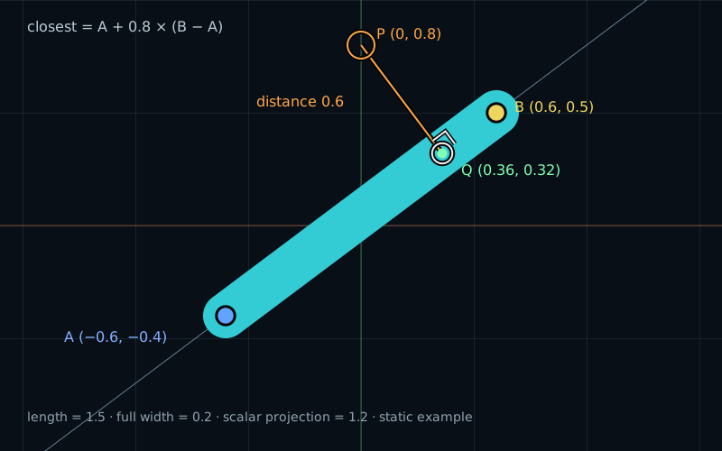
For A=(-0.6,-0.4), B=(0.6,0.5), and probe P=(0,0.8), projection gives t=0.8 and closest point Q=(0.36,0.32). The perpendicular distance from P to Q is 0.6.
A displacement → a fraction → the closest pointt = 0.8 · Q = (0.36, 0.32) · distance = 0.6

We can already draw a circle by measuring distance from a point. A rounded line needs a similar measurement, but its center can be anywhere along a segment. For each pixel, we must choose the closest center first.

The dot product from chapter 06 provides the first step. It measures how far a displacement travels along a direction. Now we will turn that number back into a displacement.

Turn the number into a vector

Start with these endpoints and a probe point in our equal-unit coordinate space:

vec2 a = vec2(-0.6, -0.4);
vec2 b = vec2( 0.6,  0.5);
vec2 p = vec2( 0.0,  0.8);
vec2 ab = b - a; // (1.2, 0.9), length 1.5
vec2 u = ab / length(ab); // (0.8, 0.6), for this nonzero ab

The displacement from A to the probe is p - a = (0.6, 1.2). Its scalar projection onto the unit direction is:

float along = dot(p - a, u);
// 0.6 * 0.8 + 1.2 * 0.6 = 1.2

That is one signed distance, in coordinate units. Multiply it by the unit direction:

vec2 projected = along * u; // (0.96, 0.72)

This is the vector projection: a displacement along the line, starting from A. It differs from the scalar projection, which is only the number 1.2. Neither one is yet a point in the scene.

Find the point on the line

Add the projected displacement to its starting point:

vec2 closest = a + projected; // (0.36, 0.32)
vec2 residual = p - closest;  // (-0.36, 0.48)
float distanceToLine = length(residual); // 0.6

The residual runs from the closest point to the probe. Its dot product with u is -0.288 + 0.288 = 0, so it is perpendicular to the line.

Why is that point closest? Move the candidate point along the line. The perpendicular gap stays the same, but an extra sideways gap appears. Those two gaps form a right triangle. Its squared distance is the perpendicular gap squared plus the extra gap squared. Adding a nonzero extra gap can only increase the distance.

This gives us the nearest point on the infinite line through A and B. It may lie before A or beyond B. A segment needs one more restriction.

Use a fraction of the segment

Chapter 05 placed a point with a + t * (b - a). We can express our projection using that same dimensionless parameter:

float t = along / length(ab); // 1.2 / 1.5 = 0.8
vec2 closest = a + t * ab;

Substitute u = ab / length(ab) into the expression for along. We divide by the segment length twice, so the denominator becomes its squared length:

float t = dot(p - a, ab) / dot(ab, ab);
// dot(p - a, ab) = 1.8
// dot(ab, ab) = 2.25
// t = 1.8 / 2.25 = 0.8

Both dot products have squared coordinate units. Their ratio has no units, exactly what we need for a fraction. This form does not need a square root or a normalized vector. The denominator must still be nonzero.

Dividing by length(ab) here would be a mistake. The numerator uses the raw ab, not its unit direction. With our values, that mistake gives 1.2 instead of 0.8 and places the candidate beyond B.

Stop at the endpoints

For a segment, clamp the fraction before constructing the closest point:

float usedT = clamp(t, 0.0, 1.0);
vec2 closest = a + usedT * ab;
float distanceToSegment = length(p - closest);

If the projection lies between the endpoints, nothing changes. If t < 0, the nearest allowed point is A. If t > 1, it is B.

Default endpoints: A=(-0.6,-0.4), B=(0.6,0.5)
ProbeRaw tClosest on lineClosest on segment
(-0.66, -0.82)-0.2(-0.84, -0.58)A
(0.66, 0.92)1.2(0.84, 0.68)B

Both probes are 0.3 units from the infinite line. Their distances to the segment are larger: about 0.42426. After clamping to an endpoint, the residual is generally not perpendicular to the line. The closest point is constrained by the segment’s ends.

Handle a collapsed segment

When A and B coincide, ab and its squared length are zero. The segment is now one point. Use A as the closest point and skip the division:

vec2 ab = b - a;
float squaredLength = dot(ab, ab);
vec2 closest = a;
if (squaredLength > 0.00000001) {
    float t = dot(p - a, ab) / squaredLength;
    closest = a + clamp(t, 0.0, 1.0) * ab;
}
float distanceToSegment = length(p - closest);

The threshold is in squared coordinate units. In this small scene, we also treat segments of length about 0.0001 or less as a point to avoid dividing by a tiny number. That is an explicit approximation, not a new projection formula. Float rounding can affect the exact threshold comparison.

Coincident points do not define an infinite line. Our Line mode uses the same point fallback and labels it clearly. It does not invent a direction.

Try it

Find the closest point.

LIVE GLSL / WEBGL 2

Move the probe, choose Line or Segment, and compare raw t with the fraction actually used. Before A and Beyond B make the difference visible. A right-angle marker appears only when the residual is perpendicular.

The view has equal units and no extra zoom: Y runs from -1 to 1. Thickness is the full width of the stroke. Numerical readouts follow the built-in formulas on the host, even when you edit the shader.

Static default example: A is (-0.6,-0.4), B is (0.6,0.5), and the probe is (0,0.8). Projection parameter 0.8 gives closest point (0.36,0.32). The distance from the probe to the segment is 0.6. The stroke's full width is 0.2.
Blue: AGold: BAmber ring: probe PMint / white ring: closest Q

Equal units; no extra zoom. Vertical range: −1 to 1. Grid: 0.5 units.

The cyan stroke has the chosen full width. A faint guide extends the supporting line. The amber connector runs from P to Q. A right-angle mark appears only when Q is an unconstrained projection and the connector has nonzero length.

Endpoint A
Endpoint B
Probe P

These four probe presets restore the default endpoints and width 0.2. They keep the current Segment / Infinite line choice.

Orientation presets use length 1.5 and full width 0.2. Horizontal uses A (−0.75,0), B (0.75,0), P (0,0.6); Vertical uses A (0,−0.75), B (0,0.75), P (0.6,0); Diagonal restores the default geometry.

Preparing the live shader.

Segment length · length(B − A)
1.50000
Squared length · dot(ab, ab)
2.25000
Raw parameter · dot(P − A, ab) / dot(ab, ab)
0.80000
Parameter used for Q
0.80000
Closest point · Q
(0.36000, 0.32000)
Residual · P − Q
(−0.36000, 0.48000)
Distance · length(P − Q)
0.60000
Signed stroke distance · distance − width / 2
0.50000
Scalar projection onto the line
1.20000
Vector projection from A onto the line
(0.96000, 0.72000)
Smoothed mask at P · before drawing overlays
0.00000

The raw parameter is inside [0,1], so clamping does not move Q. The residual is perpendicular to the supporting line.

Squared length is above 0.00000001, so the division is used.

Readouts are JavaScript float32 references for the built-in formulas; the GPU may round the last digits differently. Scalar and vector projections refer to the infinite supporting line, before clamping. Q and the distance follow the selected shape. Shader edits do not change these reference calculations.

Move with pointer or keyboard:

Selected: probe. Click or drag the selected point; clicking near a point selects it. Focus the diagram and use arrow keys for steps of 0.05; hold Shift for 0.25. On a touch screen, tap a location or use the controls; a swipe scrolls the page. All point components range from −1 to 1; an infinite-line projection may lie outside that range.

Open the complete shader edit · run · reset

The page supplies uA, uB, uProbe, positive uWidth, uMode (0 = segment, 1 = infinite line), uShowGuides, and uResolution. The closest-point calculation in main() is the lesson. Drawing helpers supply the grid, markers, and right-angle indicator.

⌘ / Ctrl + Enter to run

The editor includes supplied grid, marker, and connector helpers. The nearest-point calculation is shared by the visible stroke and the probe’s guide. The host code supplies controls and uniforms. Rendering happens when something changes.

Give the segment width

Once we have the nearest point, the circle technique from chapter 03 does the rest. Keep every pixel whose distance to the segment is less than a radius:

float radius = width * 0.5;
float signedDistance = distanceToSegment - radius;

Inside the stroke, this value is negative; on its boundary it is zero. The straight middle has full width 2 * radius. Past an endpoint, the closest point stays at that endpoint, so the boundary becomes part of a circle. This shape is a capsule.

When the endpoints coincide, it becomes a disk of the same radius. If the squared length passes our guard, Line mode extends the stroke forever instead. No separate vertical, horizontal, or diagonal drawing formula is needed.

A complete stroke shader

Paste this into the editor to see the shape without guides. Line/Segment, endpoints, and thickness still work. The soft edge is centered on the nominal boundary and spans about two drawing-buffer pixels.

#version 300 es
precision highp float;
uniform vec2 uResolution;
uniform vec2 uA;
uniform vec2 uB;
uniform float uWidth;
uniform int uMode; // 0 = segment, 1 = infinite line.
out vec4 fragColor;

void main() {
    vec2 p = (2.0 * gl_FragCoord.xy - uResolution) / uResolution.y;
    vec2 ab = uB - uA;
    float squaredLength = dot(ab, ab);
    vec2 closest = uA;
    if (squaredLength > 0.00000001) {
        float t = dot(p - uA, ab) / squaredLength;
        float usedT = uMode == 0 ? clamp(t, 0.0, 1.0) : t;
        closest = uA + usedT * ab;
    }
    float distanceToPath = length(p - closest);
    float radius = max(uWidth, 0.02) * 0.5;
    float edge = 2.0 / uResolution.y;
    float mask = 1.0 - smoothstep(radius - edge, radius + edge, distanceToPath);
    fragColor = vec4(mix(vec3(0.04, 0.06, 0.09),
                         vec3(0.20, 0.80, 0.83), mask), 1.0);
}

Distance is measured in the same coordinate units in every direction, so the thickness stays constant as the segment turns. Near the soft edge, the mask gradually changes instead of making a hard pixel-sized jump. The width control stays positive; the shader also guards its minimum.

Your turn

Use Reset lab. Start in Segment mode.

  1. Predict raw t, the closest point, and the distance for the default probe. Then choose Before A and Beyond B. Switch each one to Line mode and explain why its nearest point moves.
  2. Use the smaller shader above. Rewrite its mask using signedDistance = distanceToPath - radius and 1.0 - smoothstep(-edge, edge, signedDistance). Set the output to fragColor = vec4(vec3(mask), 1.0); to inspect the capsule mask itself.
  3. Return to Segment mode. Compare Horizontal, Vertical, and Diagonal at the same thickness. Use Reset code to restore the complete shader and try On stroke boundary: predict the signed distance and mask there.
  4. Choose Set B = A. Check that no t is reported as a valid projection and that the capsule becomes a disk. Switch to Line mode and explain why the demo still uses a point.
A hint

The raw fraction is a dot-product ratio. The segment uses its clamped value, while the line uses the original one. A full thickness of 0.2 means radius 0.1.

Check your result

The default gives t=0.8, closest point (0.36,0.32), and distance 0.6. Before A gives t=-0.2; Beyond B gives t=1.2. Segment mode stops at A or B with distance about 0.42426. Line mode gives the points in the table and distance 0.3.

Both mask expressions describe the same capsule. On stroke boundary restores width 0.2 and places the probe at (-0.06,0.13), 0.1 units from the middle of the segment. Its signed distance is zero and its soft mask is approximately 0.5. At coincidence, the nearest point is A and the shape is a disk of radius 0.1. There is no unique infinite line and no meaningful projection fraction.

What you can do now

Turn the segment without changing its thickness, move a probe beyond either endpoint, and collapse the segment without breaking the shader. You can now separate a displacement into a part along a line and a remaining perpendicular part. Next, we will use that separation to reflect a direction from a surface.