Linear Algebra for GLSL Shaders
18 / Add depth and light

Find a perpendicular
in 3D.

Two edges describe a plane. Find a direction that points away from it, then turn those edges into three perpendicular unit axes.

30–40 min with experimentsGLSL ES 3.00 / WebGL 2After chapters 04, 06, and 17
What we want to make

Give a plane its own perpendicular.

Change the edges ↓

Edit two 3D edges and watch a blue normal follow their plane. Reverse its orientation without moving the edges, and inspect the unit frame built from them.

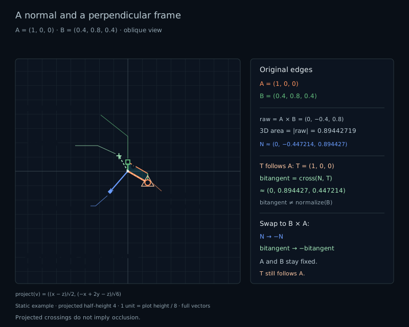
Two edges A=(1,0,0) and B=(0.4,0.8,0.4) define a parallelogram. Their cross product is (0,-0.4,0.8); its unit normal and two perpendicular unit tangents form a frame.
Two edges · one oriented perpendicularThe cross product supplies a direction and an area.

In the previous chapter we rotated a plane whose axes were already known. This time, start with two arbitrary edges. We need a third direction that is perpendicular to both, even when the edges are not perpendicular to each other.

Start with two edges

Let two vectors begin at the same origin:

vec3 edgeA = vec3(1.0, 0.0, 0.0);
vec3 edgeB = vec3(0.4, 0.8, 0.4);

The points 0, edgeA, edgeA+edgeB, and edgeB form a parallelogram. Moving along either edge stays in its plane. A perpendicular direction is called a normal. It is useful when choosing a surface orientation, constructing a camera, or calculating light later.

There are two opposite perpendicular directions. The edges alone do not choose a preferred side, but their order can. We keep the right-handed world from chapter 17: X, then Y, selects positive Z.

Build the perpendicular

GLSL provides the cross product for this job:

vec3 rawNormal = cross(edgeA, edgeB);

Unlike dot, which returns a scalar, cross returns a vec3. Its components are:

vec3 rawNormal = vec3(
    edgeA.y*edgeB.z - edgeA.z*edgeB.y,
    edgeA.z*edgeB.x - edgeA.x*edgeB.z,
    edgeA.x*edgeB.y - edgeA.y*edgeB.x
);

Each component resembles the 2D determinant from chapter 15. The three components describe signed areas in the YZ, ZX, and XY coordinate planes, with those axis orders. Together they give an oriented perpendicular in space.

Why is it perpendicular? Substitute this formula into dot(rawNormal,edgeA). Every product has an equal term with the opposite sign, so they cancel. The same happens with edgeB. This is the algebraic reason both dot products are zero in exact arithmetic.

For our edges, rawNormal=(0,−0.4,0.8). Its dot product with A is zero because its X component is zero. Its dot product with B is −0.4×0.8+0.8×0.4=0. The 0.4 component of B along A adds no new direction to the plane.

Read its length and sign

The raw cross product is generally not a unit vector:

float area = length(cross(edgeA, edgeB));
// area = length(edgeA) * length(edgeB) * sin(theta)

Here theta is the angle between the edges, from 0 to pi. The parallelogram has base length(A) and perpendicular height length(B)*sin(theta), so this is its area. Equivalently, expanding the component formula gives |A×B|²=|A|²|B|²−dot(A,B)². Using the dot-product angle formula produces the same result.

In our example the area is sqrt(0.8), approximately 0.89443. With perpendicular edges (0.5,0,0) and (0,0.5,0), the area is 0.25. The raw normal shrinks with the area, but a unit normal still has length 1.

Swap the arguments and every subtraction changes sign:

cross(edgeB, edgeA) == -cross(edgeA, edgeB); // Exact math.

The plane and its area stay the same. The normal points to the opposite side. Follow the right-hand rule: curl from the first edge toward the second through the smaller angle; your thumb gives the cross-product direction. For X and Y, the result is Z; for Y and X, it is −Z.

Decide when to normalize

Parallel or opposite edges have zero cross product. So does any pair containing a zero edge. Such inputs do not determine a unique plane normal. Do not call normalize on their cross product.

Nearly parallel edges are different: they can define a mathematical plane, but a tiny cross product amplifies rounding when normalized. The lab uses two explicit checks for its bounded inputs:

const float EPS = 0.0001;
float lenA = length(edgeA), lenB = length(edgeB);
float area = length(rawNormal);
float areaLimit = EPS * (lenA * lenB);
bool usable = lenA > EPS && lenB > EPS && area > areaLimit;
if (usable) {
    vec3 normal = rawNormal / area;
    // Build and draw the frame here.
}

The first checks reject very short edges in the lab's coordinate units. The relative area check rejects a small sine of the angle, independently of the edge lengths. These are demonstration policies, not a universal guarantee of numerical accuracy. Rejection does not mean every input is mathematically singular.

For A=(1,0,0), B=(1,0.00005,0), the area is positive, but the angular check pauses the frame. Increase B.y to 0.001 and it resumes. With B.y=0, the exact parallel pair has no normal. Rounded calculations can also produce zero through cancellation; a zero readout alone is not proof of exact collinearity.

The lab keeps the edges, raw cross product, and area available when the frame is paused. The normal and frame readouts become unavailable, rather than pretending a zero vector is a valid normal. Near the cutoff, accepted results may still show larger perpendicularity errors.

Complete a unit frame

A normal gives us one axis. Normalize A to get an in-plane tangent T. Then take another cross product:

// Only after the usable check:
vec3 N = rawNormal / area;
vec3 T = edgeA / lenA;
vec3 Bframe = cross(N, T);
mat3 frame = mat3(T, Bframe, N);

N is perpendicular to the plane, so it is perpendicular to T. Their cross product lies in the plane and is perpendicular to T. Because both inputs have length 1 and their angle is 90°, Bframe also has length 1 in exact arithmetic. These three unit, mutually perpendicular vectors form an orthonormal frame.

Simply normalizing edgeB would not work: it can still lean toward T. Our default frame is T=(1,0,0), N≈(0,−0.44721,0.89443), and Bframe≈(0,0.89443,0.44721). The new bitangent follows the part of B perpendicular to A, with the orientation chosen by the normal.

The column order (T,Bframe,N) is right-handed: cross(T,Bframe)=N. When we reverse only the normal's cross order, T stays fixed and both N and Bframe reverse. The input edges and the plane do not move.

Check the result with dot products and lengths. dot(N,A) and dot(N,B) should be close to zero; the three frame pairs should also be perpendicular, with lengths close to 1. The host readouts are float32 references for the built-in formulas, not GPU measurements. Editing the shader changes the drawing but not those references.

Try it

Change the plane. Check its normal.

LIVE GLSL / WEBGL 2

Orange and green show the two input edges. Blue shows either their raw cross product or the unit normal. The optional frame uses T along A and a corrected bitangent in the plane.

All edge components stay in [−1,1]. The square view has half-height 4: one unit is one eighth of the canvas height. Vectors keep their full lengths. Oblique uses a fixed orthographic view from the positive octant; Front and Side use the projections from chapter 17. Drawing order does not represent hidden surfaces.

Static default: A=(1,0,0), B=(0.4,0.8,0.4). Their cross product is (0,-0.4,0.8), with area about 0.89443. The unit normal is perpendicular to both edges; tangent follows A and bitangent completes the frame.
A: orange, circleB: green, squareN or raw: blue, diamondT: pale orange dashes, triangleBitangent: pale green dashes, plusGray: parallelogram spanned by A and B

Fixed view half-height 4: screen y runs from −4 to 4, with equal units in both directions. One unit is canvas height / 8. All vectors are drawn at their full lengths before projection; this view fits the complete input range.

Colored origin rings mark zero or very short screen projections, at most 0.0001. They do not imply that the 3D vector is zero. These are orthographic wireframes: crossings and drawing order do not describe occlusion or lighting.

Find the plane’s normal

Edge A · orange
Edge B · green

Frame available under the demo policy.

Presets, guard, and frame details

Tilted restores A=(1,0,0), B=(0.4,0.8,0.4). XY uses A=(1,0,0), B=(0,1,0). Parallel uses A=B=(1,0,0). Zero A uses A=(0,0,0), B=(0,1,0). Near parallel uses A=(1,0,0), B=(1,0.00005,0). Scaled uses A=(0.5,0,0), B=(0,0.5,0), with area 0.25.

Every preset selects A × B, Unit normal, and Oblique; overlay choices are preserved. Reset lab also restores every overlay. Reset code restores the shader separately. Use sliders or number fields and their native keyboard controls; the diagram has no drag handle or animation.

The demo requires both edge lengths to exceed 0.0001, and area to exceed 0.0001 × (length(A) × length(B)). The first tests reject very short edges; the relative area test rejects nearly parallel directions. This is a chosen policy for building the frame. A rejected pair can still have a nonzero mathematical cross product.

For an accepted pair, T=A/length(A) and bitangent=cross(N,T). Bitangent is not B/length(B). Swap reverses N and bitangent while keeping T and both original edges unchanged. In Raw mode, the blue arrow represents raw; the dashed pair still belongs to the unit frame when available.

Preparing the live shader.

Edge A
—
Edge B
—
Raw cross product · selected order
—
Area · length(raw)
—
Edge lengths · A, B
—
Area limit · EPS × (lenA × lenB)
—
Relative area · area / (lenA × lenB)
—
Unit normal · N
—
Tangent · T = A / lenA
—
Bitangent · cross(N,T)
—
Projected blue arrow
—
Cross order
—
dot(N,A), dot(N,B)
—
dot(T,N), dot(T,bitangent), dot(N,bitangent)
—
Frame lengths · T, bitangent, N
—

The two edges span a plane. The normalized cross product is perpendicular to both.

Oblique projects all three world components into a fixed screen plane.

A projected arrow can be shorter than its 3D vector.

These are host float32 references for the built-in formulas, not GPU measurements; shader edits do not change them. Products, sums, and the guard use float32 rounding, while actual GPU evaluation can differ slightly. Near cancellation, a rounded zero does not prove exact collinearity. Accepted frame lengths and dot checks are approximate, especially near the policy boundary.

“Undefined by this policy” means the lab skipped normalization and the frame construction. Raw and area remain available in every state. A plane area is a 3D measurement; its projected parallelogram can look smaller or collapse to a line in a particular view.

Open the complete shader edit · run · reset

The host supplies uEdgeA, uEdgeB, uSwapOrder, uRawMode, uView (0 Oblique, 1 Front, 2 Side), and three overlay flags. Show dot checks changes only the reference table. The supplied segment and arrow helpers draw the projected diagram. The cross product and guarded frame construction are in main().

⌘ / Ctrl + Enter to run

The host code supplies controls and numerical checks. The view helper is provided: it projects already constructed 3D vectors. Choosing another view can hide a component, but cannot change a dot product or area in the world.

A complete plane-normal shader

Paste this smaller shader into the editor. It keeps the edges, plane boundary, raw/unit normal, frame, and all three views. The default adds grid lines, dashed frame arrows, and distinct endpoint markers. Drawing helpers are supplied; focus on the cross products and the guard before division.

#version 300 es
precision highp float;
uniform vec2 uResolution;
uniform vec3 uEdgeA; // Each component in [-1, 1].
uniform vec3 uEdgeB; // Each component in [-1, 1].
uniform bool uSwapOrder;
uniform bool uRawMode;
uniform int uView; // 0 Oblique, 1 Front, 2 Side.
uniform bool uShowPlane;
uniform bool uShowFrame;
out vec4 fragColor;

vec2 projectPoint(vec3 world) {
    if (uView == 1) return world.xy;
    if (uView == 2) return vec2(-world.z, world.y);
    // A fixed orthographic view from the positive octant.
    return vec2((world.x-world.z)/sqrt(2.0),
                (-world.x+2.0*world.y-world.z)/sqrt(6.0));
}
float segmentDistance(vec2 p, vec2 a, vec2 b) {
    vec2 v = b-a;
    float vv = dot(v,v);
    float t = vv > 0.0 ? clamp(dot(p-a,v)/vv,0.0,1.0) : 0.0;
    return length(p-a-t*v);
}
float arrowDistance(vec2 p, vec2 tip, float pixel) {
    float len = length(tip);
    if (len <= pixel) return abs(length(p)-0.045);
    vec2 d = tip/len, n = vec2(-d.y,d.x);
    float h = min(0.15,0.3*len);
    return min(segmentDistance(p,vec2(0),tip),
        min(segmentDistance(p,tip,tip-h*d+0.5*h*n),
            segmentDistance(p,tip,tip-h*d-0.5*h*n)));
}
vec3 paintArrow(vec3 color, vec2 p, vec3 vector, vec3 ink, float pixel) {
    vec2 tip = projectPoint(vector);
    float line = 1.0-smoothstep(pixel,2.0*pixel,arrowDistance(p,tip,pixel));
    return mix(color,ink,line);
}
void main() {
    vec2 p = 4.0*(2.0*gl_FragCoord.xy-uResolution)/uResolution.y;
    float pixel = 8.0/uResolution.y;
    vec3 rawNormal = uSwapOrder ? cross(uEdgeB,uEdgeA) : cross(uEdgeA,uEdgeB);
    float lenA = length(uEdgeA), lenB = length(uEdgeB);
    float area = length(rawNormal);
    const float EPS = 0.0001;
    float areaLimit = EPS * (lenA * lenB);
    bool usable = lenA > EPS && lenB > EPS && area > areaLimit;
    vec3 color = vec3(0.035,0.055,0.08);
    vec2 a = projectPoint(uEdgeA), b = projectPoint(uEdgeB);
    vec2 sum = projectPoint(uEdgeA+uEdgeB);
    float border = min(min(segmentDistance(p,vec2(0),a),segmentDistance(p,a,sum)),
                       min(segmentDistance(p,sum,b),segmentDistance(p,b,vec2(0))));
    if (uShowPlane) color = mix(color,vec3(0.55,0.63,0.72),
        1.0-smoothstep(pixel,2.0*pixel,border));
    color = paintArrow(color,p,uEdgeA,vec3(1.0,0.57,0.28),pixel);
    color = paintArrow(color,p,uEdgeB,vec3(0.48,0.86,0.60),pixel);
    if (usable) {
        vec3 N = rawNormal / area;
        vec3 T = uEdgeA / lenA;
        vec3 Bframe = cross(N, T);
        if (uShowFrame) {
            color = paintArrow(color,p,T,vec3(1.0,0.75,0.45),pixel);
            color = paintArrow(color,p,Bframe,vec3(0.60,1.0,0.75),pixel);
        }
        if (!uRawMode) color = paintArrow(color,p,N,vec3(0.42,0.62,1.0),pixel);
    }
    // The raw vector remains available even when the unit frame is paused.
    if (uRawMode) color = paintArrow(color,p,rawNormal,vec3(0.42,0.62,1.0),pixel);
    fragColor = vec4(color,1.0);
}

Your turn

Use Reset lab and Reset code first.

  1. Choose XY. Predict the raw cross product and area. Swap cross order. Explain which vectors reverse and why the input plane stays the same.
  2. Choose Scaled. Compare Raw cross with Unit normal. Predict both lengths. Return to Tilted and use Show dot checks to verify the normal and the three unit frame axes.
  3. Choose Near parallel. Explain why the positive area does not produce a unit frame. Set B.y to 0.001, then to 0. Identify the accepted frame and the exactly parallel case. Try Zero A too.
  4. Paste the smaller shader. At Tilted, replace only vec3 Bframe = cross(N, T); with vec3 Bframe = normalize(uEdgeB);. Predict the changed bitangent arrow and calculate its dot product with T. The built-in readouts will not follow your edit. Restore the cross product.
A hint

In XY, the first two unit coordinate axes select the third. Scaling both edges by one half scales the cross product by one quarter. In Tilted, B has a nonzero X component, so merely normalizing it cannot make it perpendicular to T=(1,0,0).

Check your result

XY has raw normal (0,0,1) and area 1. Swapping gives (0,0,−1); N and Bframe reverse, T stays fixed. Scaled has raw normal (0,0,0.25), area 0.25, and unit normal (0,0,1).

Tilted has area≈0.89443, N≈(0,−0.44721,0.89443), T=(1,0,0), and Bframe≈(0,0.89443,0.44721). Their pairwise dot products are near zero and lengths near 1. Near parallel is rejected by the angular policy; B.y=0.001 is accepted, while B.y=0 makes the exact pair parallel. Zero A is rejected before normalization.

The edited bitangent becomes normalize(B)≈(0.40825,0.81650,0.40825), with dot(T,Bframe)≈0.40825. Its length is 1, but it is not perpendicular to T. Restoring cross(N,T) restores the orthonormal frame.

What you can do now

Build a plane normal and an orthonormal frame from two nonparallel edges. You can explain cross-product order and area, verify the axes with dot products, and stop before normalizing invalid input. Next, we will use three perpendicular directions to build a camera.