Linear Algebra for GLSL Shaders
19 / Add depth and light

Build a camera from
three directions.

Keep the scene still. Give the camera its own origin and axes, then describe every world point from that new point of view.

35–45 min with experimentsGLSL ES 3.00 / WebGL 2After chapters 06, 14, 17, and 18
What we want to make

Walk around a scene without moving it.

Move the camera ↓

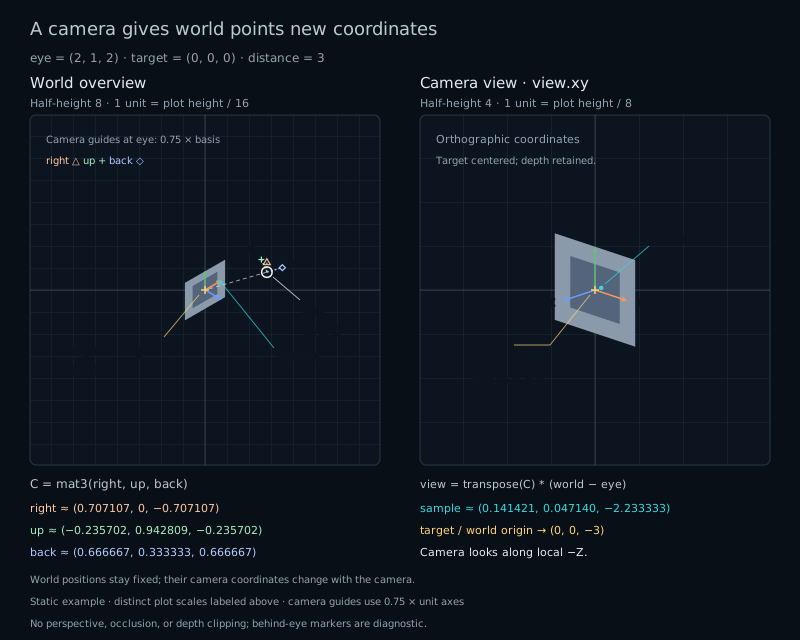
Compare a fixed world diagram with the coordinates seen from a moving camera. The target stays on the camera's negative Z axis while the card turns in the view.

A camera at (2,1,2) looks toward the origin. Its right, up, and back axes form an orthonormal frame. The fixed sample (0.6,0.3,0.4) becomes approximately (0.14142,0.04714,-2.23333) in view space.
Fixed world · moving frameSubtract the camera position, then measure along its three axes.

We have moved points through a fixed view. Now let the scene stay where it is and move the place from which we describe it. The card does not rotate when the camera goes around it. Its coordinates in the camera's frame change.

A different origin and three new axes

Keep a small card in the world XY plane, centered at the origin. Put a separate sample point at (0.6,0.3,0.4), slightly in front of that plane. We need two positions to aim the camera:

vec3 eye = vec3(2.0, 1.0, 2.0);
vec3 target = vec3(0.0);

eye is the camera's position. target is a point it looks toward. Neither value moves the card. Moving eye around target changes which side of the card faces the camera. In the world pane, the card and sample remain fixed; in the view pane, their projected arrangement changes.

This is the change of basis from chapter 9, with three axes and a translated origin. We want each point's displacement along the camera's right, up, and back directions.

Choose the direction of positive Z

We use a right-handed view frame whose camera looks along negative Z. Positive Z points backward, toward the space behind the camera. Therefore back points from target toward eye:

vec3 offset = eye - target;
float distanceToTarget = length(offset);
// Continue only when distanceToTarget > 0.0001.
vec3 back = offset / distanceToTarget;

The subtraction order matters. target-eye points forward, which would give a different sign convention. With eye=(0,0,3) and target=(0,0,0), back=(0,0,1). A point at the world origin is three units in front of the camera, so we expect its view Z to be −3.

That negative coordinate does not mean a negative distance. It says which side of the camera's origin contains the point. Later, perspective will use this sign to turn forward depth into a positive divisor.

Find right, then correct up

An aiming direction still permits the camera to roll around it. Supply an up hint to choose the remaining orientation. Usually the hint is world Y:

vec3 upHint = vec3(0.0, 1.0, 0.0);
vec3 right = normalize(cross(upHint, back));
vec3 up = cross(back, right);

The first cross product supplies a direction perpendicular to the hint and back. For the front-facing camera, cross(Y,Z)=X: right really points right. The second cross constructs the perpendicular up direction. We used the same construction to complete a frame in chapter 18.

The hint is not generally the final up axis. If the camera looks downward, world Y leans toward its back direction. The corrected up removes that component. In exact arithmetic, right, up, and back have unit length, all three pairwise dot products are zero, and cross(right,up)=back.

For eye=(2,1,2) and target=0, the distance is 3. The axes are back=(2,1,2)/3, right=(1,0,−1)/sqrt(2), and up=(−1,4,−1)/(3*sqrt(2)). The camera tilts downward while keeping a consistent orientation. Reversing the first cross order would reverse both right and the corrected up, rolling the picture by 180 degrees.

Measure from the camera

First express the world point as a displacement from eye. Then ask how much of that displacement follows each unit axis:

vec3 relative = world - eye;
vec3 view = vec3(
    dot(right, relative),
    dot(up, relative),
    dot(back, relative)
);

Each dot product is the signed coordinate along one camera axis. The view origin is eye itself: subtracting eye gives zero. A direction, such as a surface normal, has no position to translate; converting a direction uses the rotational part alone.

Try the calculation with target. Its displacement is −distanceToTarget*back. Perpendicularity makes its right and up coordinates zero. Its back coordinate is −distanceToTarget, because dot(back,back)=1. So target should become approximately (0,0,−distanceToTarget), up to floating-point rounding.

For our default camera, the sample at (0.6,0.3,0.4) becomes approximately (0.14142,0.04714,−2.23333). It sits slightly right of and above the center, in front of the camera. Its world coordinates have not changed.

Turn the three measurements into a matrix

Put the axes into GLSL's column constructor:

mat3 cameraToWorld = mat3(right, up, back);

This matrix builds a world direction from camera coordinates: it scales the three columns and adds them. We need the reverse operation to describe a world displacement in camera coordinates.

For an orthonormal matrix, its transpose is its inverse. Why? Each entry of transpose(C)*C is a dot product between two columns of C. The diagonal entries are 1; the other entries are 0. That produces the identity matrix.

vec3 view = transpose(cameraToWorld) * (world - eye);
// The reverse mapping:
vec3 worldAgain = eye + cameraToWorld * view;

Transposition exchanges rows and columns. The rows of transpose(cameraToWorld) therefore perform exactly the three dot products above. This shortcut relies on an orthonormal basis; it is not the inverse of an arbitrary scale or shear.

Notice the order: move the origin first, then change the axes. Forgetting the subtraction describes positions relative to the world's origin. Forgetting transpose applies the conversion in the wrong direction. At the Front preset the matrix is identity, so that second mistake is invisible. Oblique exposes it immediately.

Give the construction defined boundaries

If eye equals target, there is no aiming direction. The lab rejects a distance at or below 0.0001 before dividing. This cutoff belongs to the lab's coordinate scale; a rejected tiny separation may still be mathematically nonzero.

There is another boundary. Looking straight up or down makes world Y parallel to back, so their cross product vanishes. Near those directions, use world Z as the hint:

vec3 upHint = abs(back.y) > 0.99
    ? vec3(0.0, 0.0, 1.0)
    : vec3(0.0, 1.0, 0.0);

With the usual hint, the first cross has length sqrt(1-back.y*back.y), at least about 0.141 within the chosen branch. With the alternate hint, it is comfortably nonzero because back is close to Y. We can safely normalize it after the distance check.

The alternate hint gives a deterministic frame at both poles, but switching hints can change the camera's roll abruptly. This is a small teaching camera, not a continuous free-flight controller. Its hint readout makes the choice visible. A more advanced controller would need a policy for carrying orientation through such motion.

Draw view coordinates without perspective

The camera calculation returns three coordinates. For this chapter, draw view.xy directly. This is an orthographic projection: moving a point only along the camera's Z axis does not make it smaller. We are separating the camera's coordinate system from the projection applied afterward.

Negative view Z means in front of the eye plane; positive Z means behind it. The lab deliberately draws both as a coordinate diagnostic. It has no depth clipping or hidden-surface calculation, so a projected marker is not a promise that a physical camera would see that point.

The world pane uses a fixed oblique projection and a wider scale to include the camera. The view pane uses the camera's XY coordinates. Compare positions within each pane; their different scales mean that equal pixel lengths across the panes are not equal world lengths.

Try it

Move the eye. Keep the world.

Live GLSL / WebGL 2

The left pane is a fixed world diagram; the right pane plots camera view.xy. On a narrow screen, world is above view. The card spans x=±0.8, y=±0.55 at z=0, and the cyan sample stays at (0.6,0.3,0.4).

World half-height is 8; view half-height is 4, with equal X/Y units within each pane. Edit eye components in [−4,4] and target components in [−1,1]. Orbit yaw places eye on a defined path around the current target: horizontal radius sqrt(8), height 1. It replaces a custom eye position; manual eye or target edits leave that path until you use Orbit again.

Static default camera: eye (2,1,2), target (0,0,0), distance 3. The fixed world sample (0.6,0.3,0.4) has camera coordinates about (0.14142,0.04714,-2.23333).
World · fixed oblique view
half-height 8
Camera view · view.xy
half-height 4
Eye: white ringTarget: gold crossFixed world sample: cyan dotWorld X: orange circleWorld Y: green squareWorld Z: blue diamondCamera right / up / back: pale dashed guides at eye

The panels use different fixed scales, with equal X/Y units inside each panel. World: one unit is panel height / 16. Camera view: one unit is panel height / 8. The wireframe card stays at world corners (±0.8,±0.55,0), and the sample stays at (0.6,0.3,0.4).

World axes have length 1. Camera guides are shortened to 0.75 of each unit column: right has a triangle, up a plus, and back a diamond. Small rings mark zero or nearly zero projected axes. Camera guides appear only in the World panel.

Both views are orthographic diagnostics with no perspective, hidden-surface removal, or depth clipping. A point behind the eye is still plotted. Crossings and drawing order do not imply occlusion.

Build the camera frame

Eye · world position
Target · world position
Orbit · places the eye on a fixed path

Orbit path · yaw 45°; horizontal radius √8 and height 1 above target.

Camera frame available.

Orbit, presets, and pole behavior

Editing yaw sets eye=target+(√8 sin(yaw),1,√8 cos(yaw)). This path has horizontal radius √8, height 1, and distance 3 from the target. It fits the eye controls for every target in range. No orbit animation runs.

Manual eye or target edits switch to Custom and keep the other coordinates unchanged. The yaw control then records the last orbit input; it does not describe the custom eye. Edit yaw again to place the eye on the orbit path.

Front uses eye=(0,0,3). Quarter orbit uses (√8,1,0) and yaw 90°. Oblique uses (2,1,2) and yaw 45°. Above and Below use (0,3,0) and (0,−3,0). These five presets set target=(0,0,0). Eye = target copies the current target into the eye. Presets preserve overlays.

When eye-target distance is at most 0.0001, the lab skips the camera basis and camera-view geometry. For an accepted distance, upHint is world Y unless abs(back.y)>0.99, when it becomes world Z. Switching hints can create a sudden roll change; this policy does not promise continuous pole motion.

Reset lab restores Oblique and every overlay; Reset code restores the shader separately. Use sliders or number fields with their native keyboard controls. The panels have no drag handles.

Preparing the live shader.

Eye · world
—
Target · world
—
Distance · length(eye−target)
—
Selected upHint
—
C[0] · right
—
C[1] · up
—
C[2] · back
—
Column lengths · right, up, back
—
Pair dots · right/up, right/back, up/back
—
Fixed sample · world
—
Sample · transpose(C) × (world−eye)
—
Sample · three dot products
—
Target · view coordinates
—
Eye · view coordinates
—
Sample depth classification
—
Target depth classification
—

The world geometry stays fixed. The camera looks along its local −Z direction, opposite the back column.

World Y is the up hint. It chooses roll; the finished up column is perpendicular to back.

These are host float32 references for the built-in formulas, not GPU measurements; shader edits do not change them. Uniform inputs, vector differences, products, sums, and guard comparisons use float32 rounding. Actual GPU results can differ slightly, particularly near thresholds. Tiny residuals around zero are expected.

C contains the camera axes as world-space columns. transpose(C) reads components along those columns after subtracting eye. Negative view.z is in front of the eye; positive view.z is behind it. Points in the view plane have view.z≈0. The diagnostic drawing keeps all of them visible.

Open the complete shader edit · run · reset

The host supplies uEye, uTarget, the responsive uStacked flag, and three overlay flags. Orbit only changes uEye; it does not transform the card. The complete supplied segment and arrow helpers draw both orthographic panels. The camera basis is guarded before normalization, and projectScene() contains the view transform.

⌘ / Ctrl + Enter to run

The camera in a smaller complete shader

Paste this entire fragment shader into the editor. It keeps the two panes, fixed geometry, controls, and guarded camera construction. The editor's default adds arrowheads, distinct axis markers, and other diagram styling. Both versions receive the same uniforms; uStacked follows the responsive panel layout. World axes have length 1; the camera guides are drawn at 0.75 of their unit lengths.

#version 300 es
precision highp float;
uniform vec2 uResolution;
uniform vec3 uEye;
uniform vec3 uTarget;
uniform bool uStacked;
uniform bool uShowGrid;
uniform bool uShowWorldAxes;
uniform bool uShowCameraAxes;
out vec4 fragColor;
const float EPS = 0.0001;

bool cameraFrame(out mat3 cameraToWorld) {
    cameraToWorld = mat3(1.0); // Never used as a view frame on failure.
    vec3 offset = uEye - uTarget;
    float distanceToTarget = length(offset);
    if (distanceToTarget <= EPS) return false;
    vec3 back = offset / distanceToTarget;
    vec3 upHint = abs(back.y) > 0.99
        ? vec3(0.0, 0.0, 1.0) : vec3(0.0, 1.0, 0.0);
    vec3 right = normalize(cross(upHint, back));
    vec3 up = cross(back, right);
    cameraToWorld = mat3(right, up, back);
    return true;
}
vec2 worldDiagram(vec3 world) {
    return vec2((world.x + world.z) / sqrt(2.0),
        (world.x + 2.0*world.y - world.z) / sqrt(6.0));
}
vec2 projectPoint(vec3 world, bool viewPane, mat3 cameraToWorld) {
    if (!viewPane) return worldDiagram(world);
    vec3 view = transpose(cameraToWorld) * (world - uEye);
    return view.xy; // Orthographic diagnostic: no depth clipping.
}
float segment(vec2 p, vec2 a, vec2 b) {
    vec2 edge = b - a;
    float squaredLength = dot(edge, edge);
    if (squaredLength <= 0.00000001) return length(p - a);
    float t = clamp(dot(p - a, edge) / squaredLength, 0.0, 1.0);
    return length(p - a - t*edge);
}
float line(float d, float pixel) {
    return 1.0 - smoothstep(pixel, 2.0*pixel, d);
}
void main() {
    // Wide: world left, view right. Tall: world top, view bottom.
    bool stacked = uStacked;
    vec2 size = stacked ? vec2(uResolution.x, uResolution.y*0.5)
                        : vec2(uResolution.x*0.5, uResolution.y);
    bool viewPane = stacked ? gl_FragCoord.y < size.y
                            : gl_FragCoord.x >= size.x;
    vec2 origin = stacked ? vec2(0.0, viewPane ? 0.0 : size.y)
                          : vec2(viewPane ? size.x : 0.0, 0.0);
    float halfHeight = viewPane ? 4.0 : 8.0;
    vec2 p = halfHeight * (2.0*(gl_FragCoord.xy-origin)-size) / size.y;
    float pixel = 2.0*halfHeight / size.y;
    vec3 color = vec3(0.035, 0.055, 0.08);
    if (uShowGrid) {
        vec2 grid=abs(mod(p+0.5,1.0)-0.5);
        color=mix(color,vec3(0.22,0.28,0.34),line(min(grid.x,grid.y),pixel)*0.4);
    }
    mat3 cameraToWorld;
    bool valid = cameraFrame(cameraToWorld);
    if (viewPane && !valid) {
        float warning = min(segment(p, vec2(-0.3), vec2(0.3)),
            segment(p, vec2(-0.3,0.3), vec2(0.3,-0.3)));
        fragColor = vec4(mix(color, vec3(1.0,0.5,0.3), line(warning,pixel)),1.0);
        return; // Never project through an invalid frame.
    }
    vec3 a=vec3(-0.8,-0.55,0.0), b=vec3(0.8,-0.55,0.0);
    vec3 c=vec3(0.8,0.55,0.0), d=vec3(-0.8,0.55,0.0);
    vec2 pa=projectPoint(a,viewPane,cameraToWorld);
    vec2 pb=projectPoint(b,viewPane,cameraToWorld);
    vec2 pc=projectPoint(c,viewPane,cameraToWorld);
    vec2 pd=projectPoint(d,viewPane,cameraToWorld);
    float card=min(min(segment(p,pa,pb),segment(p,pb,pc)),
                   min(segment(p,pc,pd),segment(p,pd,pa)));
    // One diagonal makes the card's orientation visible.
    card=min(card,segment(p,pa,pc));
    color=mix(color,vec3(0.75,0.82,0.88),line(card,pixel));
    vec2 zero=projectPoint(vec3(0.0),viewPane,cameraToWorld);
    for (int i=0;i<3;i++) {
        vec3 axis=vec3(0.0); axis[i]=1.0;
        vec3 tint=i==0?vec3(1.0,0.57,0.28)
            :i==1?vec3(0.4,0.87,0.56):vec3(0.4,0.66,1.0);
        vec2 end=projectPoint(axis,viewPane,cameraToWorld);
        if (uShowWorldAxes) color=mix(color,tint,line(segment(p,zero,end),pixel));
        if (valid && !viewPane && uShowCameraAxes) {
            vec2 eye=worldDiagram(uEye);
            vec2 tip=worldDiagram(uEye+0.75*cameraToWorld[i]);
            color=mix(color,mix(tint,vec3(1.0),0.45),line(segment(p,eye,tip),pixel));
        }
    }
    vec2 target=projectPoint(uTarget,viewPane,cameraToWorld);
    vec2 samplePoint=projectPoint(vec3(0.6,0.3,0.4),viewPane,cameraToWorld);
    if (!viewPane) {
        vec2 eye=worldDiagram(uEye);
        color=mix(color,vec3(0.5),line(segment(p,eye,target),pixel)*0.4);
        color=mix(color,vec3(0.95),line(abs(length(p-eye)-5.0*pixel),pixel));
    }
    color=mix(color,vec3(1.0,0.81,0.31),line(abs(length(p-target)-4.0*pixel),pixel));
    color=mix(color,vec3(0.24,0.88,0.94),1.0-smoothstep(3.0*pixel,4.0*pixel,length(p-samplePoint)));
    fragColor=vec4(color,1.0);
}

Your turn

Use Reset lab and Reset code first.

  1. Choose Front. Predict the target's view coordinates and the sample's view Z. Compare the three dot products with the matrix result.
  2. Return to Oblique and move Orbit yaw. Predict which world positions will change. Check that the target stays approximately (0,0,−3), the frame lengths stay near 1, and its pairwise dot products stay near zero.
  3. Choose Above, then Below. Identify the selected up hint and explain why world Y cannot be used there. Choose Eye = target and verify that the frame and view readouts become unavailable before normalization.
  4. Paste the smaller complete shader from this chapter into the editor. At Oblique, replace transpose(cameraToWorld) with cameraToWorld in the point conversion. Predict whether target remains centered. Run the change, then restore the transpose.
A hint

target-eye is a negative multiple of back. Orbit moves eye around target, while the card and sample stay in world space. The columns of cameraToWorld build a world displacement from view coordinates; they do not measure its components in the reverse direction. Shader edits change the drawing, while the host readouts keep using the built-in formulas.

Check your result

Front gives target=(0,0,−3) and sample=(0.6,0.3,−2.6). Dot and matrix results agree up to rounding. The orbit's horizontal radius sqrt(8) and height 1 give distance 3 at every yaw; only the camera moves.

Above and Below both choose world Z as the up hint. Their right axes are −X and +X, respectively, and their corrected up is +Z. Eye = target has no aiming direction, so no frame is constructed. At default Oblique, omitting transpose sends target to about (−2.51184,−1.60948,0.31658) instead of (0,0,−3). It moves off center and even gets the depth sign wrong.

What you can do now

Build a right-handed camera frame and convert world points to view space. You can explain the target's negative Z coordinate, match the matrix result to three dot products, and distinguish camera motion from object motion. Next, we will make distance affect the projected size.