Linear Algebra for GLSL Shaders
17 / Add depth and light

One more
coordinate.

Turn a flat plane until it becomes a line on the screen. Then look from the side. The plane is still there; the screen was hiding one of its dimensions.

25–35 min with experimentsGLSL ES 3.00 / WebGL 2After chapters 04, 10–11, and 16
What we want to make

One world. Two ways to see it.

Turn the plane ↓

Rotate a wireframe plane and its three axes. A gold point can move away from the plane. Compare front and side views while keeping its full world coordinates visible.

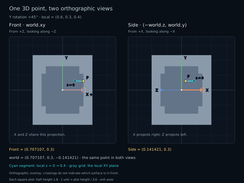
A point and wireframe plane rotated 45 degrees around Y are shown from the front and side. World point (0.70711,0.3,-0.14142) has front projection (0.70711,0.3) and side projection (0.14142,0.3).
Rotation changes the world · projection changes the pictureA short arrow on the screen can still be a unit vector in space.

Until now, our drawings lived in a plane. To turn that plane away from us, we need to describe where each point goes outside it. Add one coordinate, keep the same vector operations, and give the screen a separate job.

Give Z a spatial meaning

A spatial point now has three coordinates:

vec3 localPoint = vec3(0.6, 0.3, 0.4);

X and Y measure the familiar horizontal and vertical displacements. Z measures displacement along a third perpendicular axis. In our front view, positive Z points toward us. The system is right-handed: point your right thumb along a positive rotation axis; your curled fingers give the positive turning direction.

This Z is different from the extra component in chapter 16. There, vec3(x,y,w) represented a 2D point or direction in homogeneous coordinates. Here, vec3(x,y,z) contains three spatial components. A mat3 now holds a 3D linear transform. A full 3D affine transform would need a fourth homogeneous component and a mat4.

The type does not decide whether a vector represents a point or a direction. Subtract two positions to get a displacement. Translation affects positions, while a rotation acts on both positions relative to the origin and directions:

vec3 direction = pointB - pointA;
vec3 worldPoint = R * localPoint;
vec3 worldDirection = R * direction;

Length also extends directly: sqrt(x*x+y*y+z*z). Our sample (0.6,0.3,0.4) has length sqrt(0.61), about 0.78102. The old functions still work:

float distanceFromOrigin = length(localPoint);
float agreement = dot(a, b); // a.x*b.x + a.y*b.y + a.z*b.z
vec3 unitDirection = length(direction) > 0.0
    ? normalize(direction) : vec3(0.0);

The zero fallback avoids normalizing a vector without a direction. In this lab the selected point is never the zero vector, because its local X and Y stay at 0.6 and 0.3.

Build from three axes

The standard basis now contains X=(1,0,0), Y=(0,1,0), and Z=(0,0,1). A point is x copies of X, y copies of Y, and z copies of Z. A matrix records where those three basis vectors go:

mat3 R = mat3(axisX, axisY, axisZ);
vec3 world = R * local;
// world = local.x*axisX + local.y*axisY + local.z*axisZ;

The constructor takes columns, just as before. Each column now has three spatial components. R[2] is the transformed Z axis; it is no longer a translation column. The lab colors X orange, Y green, and Z blue, and lists the complete columns below the picture.

A pure rotation keeps these axes perpendicular and one unit long. This preserves angles and lengths in the world. Their projections onto a flat screen need not remain perpendicular or have equal visible lengths.

Turn around Y

A rotation around Y leaves the Y component unchanged and mixes X with Z. At a positive quarter turn, X goes toward negative Z, while Z goes toward positive X. At an arbitrary angle, those rotated axes become (c,0,−s) and (s,0,c), where c=cos(angle) and s=sin(angle):

mat3 rotationY(float angle) {
    float c = cos(angle), s = sin(angle);
    return mat3(vec3(c, 0.0, -s),
                vec3(0.0, 1.0, 0.0),
                vec3(s, 0.0, c));
}

Expand the product once to see what each coordinate does:

world.x = c*local.x + s*local.z;
world.y = local.y;
world.z = -s*local.x + c*local.z;

At 90°, the sample (0.6,0.3,0.4) becomes (0.4,0.3,−0.6). Its squared length is still 0.61. More generally, expanding world.x²+world.z² cancels the mixed terms and leaves (c²+s²)(local.x²+local.z²). Since c²+s²=1 and Y is unchanged, the rotation preserves length.

The unchanged axis is also visible in the matrix: its second column remains (0,1,0). Angles enter GLSL in radians. The interface converts degrees once; 90° becomes pi/2. Tiny residual components near zero are normal floating-point results.

Choose what the screen keeps

Our screen has two coordinates. The simplest front view keeps world X and Y:

vec2 front = world.xy;

This is an orthographic projection. It does not divide by depth, so objects do not get smaller when moved away from the viewer. Points with the same X and Y overlap even if their Z coordinates differ. One projected position cannot uniquely tell us the original 3D position.

The side view looks from positive X toward the origin. Keep Y pointing up and let negative Z point right:

vec2 side = vec2(-world.z, world.y);

The minus sign chooses this screen orientation. Switching views does not change R or worldPoint. It only changes which components we display. At Y=90°, the transformed X axis is (0,0,−1): Front shows (0,0), while Side shows (1,0). Its world length remains 1 in both views.

The wireframe plane behaves the same way. It starts in local XY with z=0. At a Y quarter turn, Front sees it edge-on as a vertical line; Side sees its full rectangle. This is not the singular collapse from chapter 15. The 3D rotation is invertible. Information is discarded afterward by the projection.

Likewise, at Identity, changing point.z does nothing to the gold marker in Front. Switch to Side to see that movement. The cyan segment connects the point to the rotated location of (0.6,0.3,0), making its displacement from the original plane visible when the view allows it.

Rotate around another axis

To rotate around Z, keep Z fixed and apply our familiar 2D rotation to X and Y. Write the images of the basis vectors as columns:

mat3 rotationZ(float angle) {
    float c = cos(angle), s = sin(angle);
    return mat3(vec3(c, s, 0.0),
                vec3(-s, c, 0.0),
                vec3(0.0, 0.0, 1.0));
}

At +90°, X becomes Y, Y becomes −X, and Z stays Z. The point becomes (−0.3,0.6,0.4). Rotation around X follows the same construction: X stays fixed, Y becomes (0,c,s), and Z becomes (0,−s,c). At +90°, our point becomes (0.6,−0.4,0.3).

These are rotations about the fixed world origin. We choose one axis at a time here. Composing several 3D rotations follows the same right-to-left rule as chapter 13; their order generally matters too.

Try it

Rotate in space. Compare the views.

LIVE GLSL / WEBGL 2

The local plane lies at z=0. The point is (0.6,0.3,point.z). Choose a rotation axis and angle, then switch Front and Side without changing the world.

The square view has fixed half-height 1.8; one unit is 1/3.6 of the canvas height. All allowed geometry fits. This wireframe drawing has no hidden-surface removal or lighting: crossing lines do not indicate which object is nearer.

Static Y45 comparison: local point (0.6,0.3,0.4) rotates to world (0.70711,0.3,-0.14142). Front projects to (0.70711,0.3); Side from positive X projects to (0.14142,0.3).
X: orange, circular endpointY: green, square endpointZ: blue dashed, diamond endpointGold: rotated 3D point, projectedCyan: projected change from z=0Gray: rotated local XY wireframe

Fixed view half-height 1.8: y runs from −1.8 to 1.8 with equal screen-plane units. One unit is canvas height / 3.6. The local XY plane has corners (±0.8,±0.55,0). Unit axes, plane, and point fit throughout the controls.

Colored rings at the origin mark axes whose projected length is at most 0.0001. Their 3D lengths remain 1. Endpoint shapes and dashed Z distinguish overlapping axes. This is an orthographic wireframe: crossings and drawing order do not describe front/back surfaces, lighting, or hidden objects.

Rotate in three dimensions

Rotation and point depth
R · rows shown, columns colored X / Y / Z
R[0] · XR[1] · YR[2] · Z
———
———
———
Preset and projection details

Every preset selects Front. Identity sets Y rotation to 0° and z=0.4. Quarter Y, Quarter Z, and Quarter X use +90° about their named axis, with z=0.4. Depth only uses Y0° and z=1. Oblique restores Y45° and z=0.4.

Ordinary axis, angle, or depth edits preserve the selected view. The local point always has x=0.6 and y=0.3. Front displays world.xy; Side displays (−world.z,world.y). These are two orthographic views of the same world, without perspective scaling.

Presets preserve overlay choices. Reset lab restores Oblique, Front, and all overlays. Reset code restores the shader separately. Use the sliders or number fields and their native keyboard controls; the diagram has no drag handle or animation.

Preparing the live shader.

Local point · (0.6,0.3,z)
(0.60000, 0.30000, 0.40000)
World point · R*local
(0.70711, 0.30000, -0.14142)
Projected point · selected view
(0.70711, 0.30000)
Point length · local, world
0.78102, 0.78102
Rotated world X · R[0]
(0.70711, 0.00000, -0.70711)
Rotated world Y · R[1]
(0.00000, 1.00000, 0.00000)
Rotated world Z · R[2]
(0.70711, 0.00000, 0.70711)
X-axis length · world, projected
1.00000, 0.70711
Projected reference with local z=0
(0.42426, 0.30000)
Projected depth displacement
(0.28284, 0.00000)

Rotation about Y keeps the Y axis fixed and turns the X/Z plane. Positive Y rotation sends +X toward −Z in this right-handed world.

Front looks from +Z toward the origin. Screen right is +X and up is +Y: projection=world.xy. World Z remains part of the 3D point even though this view omits it.

An axis can shrink or disappear in a 2D projection while retaining its full 3D length.

These are host float32 references for the built-in formulas, not GPU measurements; shader edits do not change them. Trigonometric and rounding results may differ slightly on the GPU, so nominal zero components can appear as tiny nonzero values. The colored table contains three spatial coordinates, not the homogeneous translation columns from the previous chapter.

World vectors are rotated before they are projected. Rotation preserves 3D lengths within rounding. A shorter projected vector reflects a dropped viewing-direction component; there is no normalization or perspective division. The cyan line can collapse to a point when this view hides the local depth change.

Open the complete shader edit · run · reset

The host supplies uAxis (0 X, 1 Y, 2 Z), uAngle in radians, uPointZ, uSideView, and three overlay flags. The shader rotates vec3 points and basis columns, then projects them into the screen plane. Supplied segment/arrow helpers draw the complete diagram; no inverse mapping, hidden-surface removal, or lighting is used.

⌘ / Ctrl + Enter to run

The host code supplies the controls and numerical references. The shader transforms known points forward, projects their endpoints, then measures each pixel's distance from those 2D lines. It does not try to invert a projection that has discarded a coordinate.

A complete 3D wireframe shader

Paste this smaller shader into the editor. It keeps all three rotations, both views, the plane boundary, axes, depth segment, and point. The default adds grid lines and extra axis markers for overlapping projections. Drawing helpers are supplied; focus on the columns and projectPoint.

#version 300 es
precision highp float;
uniform vec2 uResolution;
uniform float uAngle; // Radians, in [-pi, pi].
uniform float uPointZ; // Local spatial Z, in [-1, 1].
uniform int uAxis; // 0 = X, 1 = Y, 2 = Z.
uniform bool uSideView;
uniform bool uShowPlane;
uniform bool uShowAxes;
out vec4 fragColor;

mat3 rotationX(float a) {
    float c = cos(a), s = sin(a);
    return mat3(vec3(1,0,0), vec3(0,c,s), vec3(0,-s,c));
}
mat3 rotationY(float a) {
    float c = cos(a), s = sin(a);
    return mat3(vec3(c,0,-s), vec3(0,1,0), vec3(s,0,c));
}
mat3 rotationZ(float a) {
    float c = cos(a), s = sin(a);
    return mat3(vec3(c,s,0), vec3(-s,c,0), vec3(0,0,1));
}
vec2 projectPoint(vec3 world) {
    return uSideView ? vec2(-world.z, world.y) : world.xy;
}
float segmentDistance(vec2 p, vec2 a, vec2 b) {
    vec2 v = b-a;
    float vv = dot(v,v);
    float t = vv > 0.0 ? clamp(dot(p-a,v)/vv,0.0,1.0) : 0.0;
    return length(p-a-t*v);
}
float axisDistance(vec2 p, vec2 tip, float pixel) {
    float len = length(tip);
    if (len <= pixel) return abs(length(p)-0.04);
    vec2 d = tip/len, n = vec2(-d.y,d.x);
    float h = min(0.12,0.3*len);
    return min(segmentDistance(p,vec2(0),tip),
        min(segmentDistance(p,tip,tip-h*d+0.5*h*n),
            segmentDistance(p,tip,tip-h*d-0.5*h*n)));
}
float ink(float distanceToLine, float width, float pixel) {
    return 1.0-smoothstep(width,width+pixel,distanceToLine);
}
void main() {
    vec2 p = 1.8*(2.0*gl_FragCoord.xy-uResolution)/uResolution.y;
    float pixel = 3.6/uResolution.y;
    mat3 R = uAxis == 0 ? rotationX(uAngle)
           : uAxis == 1 ? rotationY(uAngle) : rotationZ(uAngle);
    vec3 world = R*vec3(0.6,0.3,uPointZ);
    vec2 point = projectPoint(world);
    vec3 color = vec3(0.035,0.055,0.08);
    vec2 a = projectPoint(R*vec3(-0.8,-0.55,0));
    vec2 b = projectPoint(R*vec3( 0.8,-0.55,0));
    vec2 c = projectPoint(R*vec3( 0.8, 0.55,0));
    vec2 d = projectPoint(R*vec3(-0.8, 0.55,0));
    float frame = min(min(segmentDistance(p,a,b),segmentDistance(p,b,c)),
                      min(segmentDistance(p,c,d),segmentDistance(p,d,a)));
    if (uShowPlane) color = mix(color,vec3(0.56,0.64,0.73),ink(frame,pixel,pixel));
    float stem = segmentDistance(p,projectPoint(R*vec3(0.6,0.3,0)),point);
    color = mix(color,vec3(0.25,0.87,0.93),ink(stem,pixel,pixel));
    if (uShowAxes) {
        for (int i=0; i<3; i++) {
            vec2 tip = projectPoint(R[i]);
            vec3 axisColor = i == 0 ? vec3(1.0,0.57,0.28)
                           : i == 1 ? vec3(0.48,0.86,0.60) : vec3(0.42,0.62,1.0);
            float width = (2.2-0.6*float(i))*pixel;
            color = mix(color,axisColor,ink(axisDistance(p,tip,pixel),width,pixel));
        }
    }
    float marker = 1.0-smoothstep(0.035,0.035+pixel,length(p-point));
    color = mix(color,vec3(1.0,0.81,0.31),marker);
    fragColor = vec4(color,1.0);
}

Your turn

Use Reset lab and Reset code first.

  1. Choose Quarter Y. Predict the three world components of the X axis and its length. Compare Front with Side. Explain why one picture shows a nearly vanished arrow without a collapsed 3D axis.
  2. Choose Depth only. Change point.z from 1 to −1 in Front, then in Side. Which world coordinate changes? Which screen coordinate changes? Explain the unchanged front picture.
  3. Return to Oblique. Compare the local and world lengths of the selected point. Change the rotation axis and angle. Predict whether either length should change, and distinguish these from the displayed length of the projected X axis.
  4. Without looking at rotationZ, write the images of X, Y, and Z after a Z rotation. Assemble those columns in your own rotationZ function and replace that helper in the smaller shader. Choose Quarter Z and run it. Predict the gold marker and the unchanged axis before comparing with the reference.
A hint

Front discards world Z; Side discards world X and reverses Z for its horizontal coordinate. A Z rotation leaves the third coordinate alone and uses the familiar 2D formula for the first two. Editing the shader changes the drawing, while the numerical readouts continue to show the built-in reference formulas.

Check your result

Quarter Y sends X to (0,0,−1), with world length 1. Its projected length is 0 in Front and 1 in Side, up to rounding. Depth only keeps Front at (0.6,0.3); Side moves from (−1,0.3) to (1,0.3).

At Oblique, the sample becomes approximately (0.70711,0.3,−0.14142), and both 3D lengths are 0.78102. Rotation preserves this length at every angle. For rotationZ, the columns are (c,s,0), (−s,c,0), and (0,0,1). Quarter Z sends the sample to (−0.3,0.6,0.4); Front shows (−0.3,0.6), and the Z axis stays (0,0,1).

What you can do now

Rotate a 3D point around an axis and separate its world position from its projection. You can construct the rotation from three columns and explain why a unit axis can disappear from one view. Next, we will build a direction perpendicular to a plane.