Linear Algebra for GLSL Shaders
20 / Add depth and light

Why distant things
look smaller.

Two equal cards. Two different depths. Build the projection that makes distance visible, then follow a real mesh from its vertices to the screen.

35–45 min with experimentsGLSL ES 3.00 / WebGL 2After chapters 16 and 19
What we want to make

Let depth change the picture.

Compare the cards ↓

Move the camera, change its field of view, and compare perspective with orthographic projection. A local checker pattern follows the tilted cards through the real vertex and fragment stages.

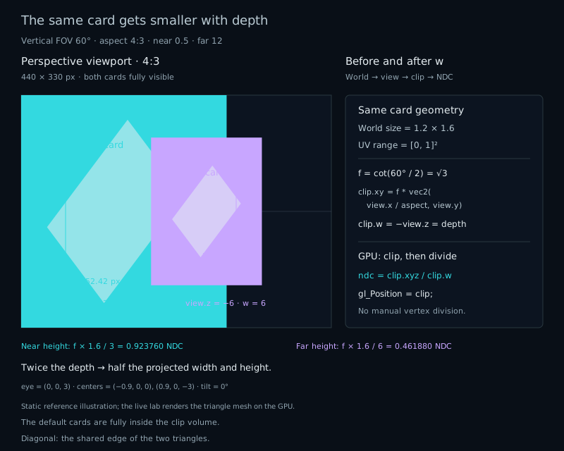
Two identical cards at forward depths 3 and 6. Perspective makes the farther card half as tall and half as wide; orthographic projection keeps their sizes equal. Clip coordinates are divided by w after clipping.
Same geometry · different depthThe matrix prepares clip coordinates. Division by w produces perspective.

The camera from the previous chapter changed our coordinate system, but distance did not change the size of the picture. Now put two identical cards at different depths. We want the farther one to occupy less of the screen, while both keep their proportions.

Start with two equal cards

Each card is 1.2 units wide and 1.6 units tall. Their world centers are (−0.9,0,0) and (0.9,0,−3). The camera sits at (0,0,3) and looks along −Z, so their forward depths are 3 and 6. In Perspective mode, the farther card is half as tall and half as wide.

Choose Orthographic. Both cards now have equal projected sizes. Their world geometry did not change; we changed the rule that converts view coordinates into a screen picture. That distinction separates the camera from its projection.

Divide by forward depth

Imagine an image plane one unit in front of the camera. A ray from the eye through a view-space point crosses that plane. Similar triangles give the intersection: horizontal displacement divided by forward depth, and the same for vertical displacement.

float depth = -view.z; // Positive for points in front.
vec2 projected = view.xy / depth;

A point at (1,0,−2) lands at horizontal coordinate 0.5. At (1,0,−4), it lands at 0.25. Doubling depth halves the projected displacement. This formula requires positive depth; a point at the eye plane would divide by zero.

Depth is a component along the camera's forward direction, not the Euclidean distance from eye to point. Two points with equal view Z share the same scale even if one is farther to the side.

Choose how much fits vertically

The vertical field of view, or FOV, is the angle between the top and bottom of the visible cone. At depth 1, its upper edge lies at tan(FOV/2). To map that edge to normalized screen coordinate +1, divide by this extent:

float focal = 1.0 / tan(0.5 * radians(verticalFovDegrees));
vec2 ndcXY = focal * view.xy / -view.z;
ndcXY.x /= aspect; // viewport width / viewport height

A narrower FOV gives a larger focal factor and a larger picture. At 60°, focal=sqrt(3). At 90°, focal=1, so every projected size becomes 1/sqrt(3), about 0.57735, of its former size. Halving the angle does not generally double the scale: the tangent is nonlinear.

The aspect correction makes one unit occupy the same number of pixels horizontally and vertically. X maps across the viewport width, while Y maps across its height; dividing X by width/height cancels that difference. Resize the viewport or change Aspect and the card keeps its shape. A narrow viewport may cut off its sides, which is clipping rather than stretching.

Prepare the division with a mat4

We add one more coordinate again, as in chapter 16. A 3D position therefore needs four components. This time the fourth coordinate will carry depth. The projection matrix produces clip coordinates, with clip.w=−view.z. WebGL performs the division later.

Let nearDistance and farDistance be positive distances, with nearDistance smaller than farDistance. Our lab fixes them at 0.5 and 12. The matrix below uses GLSL's column constructor:

float n = nearDistance, f = farDistance;
float k = 1.0 / tan(0.5 * verticalFovRadians);
mat4 projection = mat4(
    vec4(k / aspect, 0.0, 0.0, 0.0),
    vec4(0.0, k, 0.0, 0.0),
    vec4(0.0, 0.0, (f+n)/(n-f), -1.0),
    vec4(0.0, 0.0, 2.0*f*n/(n-f), 0.0)
);
vec4 clip = projection * vec4(view, 1.0);

The first two rows produce k*view.x/aspect and k*view.y. The last row produces −view.z. Thus dividing clip.xy by clip.w gives exactly our similar-triangle formula. The mat4 multiplication itself is linear in four-dimensional homogeneous coordinates; the subsequent division is nonlinear.

The Z coefficients have a separate job. Write clip.z=A*view.z+B. Requiring the near plane to become NDC Z=−1 and the far plane to become +1 gives A=(f+n)/(n−f) and B=2fn/(n−f). Depth between them maps nonlinearly. At our depths 3 and 6, NDC Z is approximately 0.73913 and 0.91304. These are not view Z or the default depth-buffer values, which lie in [0,1].

Clip first, divide afterward

For a point to lie inside the clip volume, all three clip components must lie between −w and +w:

-clip.w <= clip.x && clip.x <= clip.w
-clip.w <= clip.y && clip.y <= clip.w
-clip.w <= clip.z && clip.z <= clip.w

WebGL clips triangles against these six planes before dividing by w. A triangle can cross a boundary: the GPU keeps the inside portion and creates vertices along the intersection. One outside corner does not mean the whole card disappears.

After clipping, xyz/w produces normalized device coordinates, or NDC. Their visible range is [−1,1] on each axis. Viewport mapping then turns XY into pixel positions. Keep the spaces in order: local → world → view → clip → NDC → viewport.

Do not predivide gl_Position and replace its w with 1. That changes the homogeneous clipping information and how values are interpolated across triangles. Supply the original clip vector and let the pipeline finish the projection.

Give WebGL four vertices

Earlier labs drew a fullscreen triangle and calculated a diagram inside its fragment shader. This one supplies a real card mesh: four local positions, four UV coordinates, and two indexed triangles.

// position.xyz, uv.xy: interleaved vertex attributes
const vertices = new Float32Array([
  -0.6, -0.8, 0,  0, 0,
   0.6, -0.8, 0,  1, 0,
   0.6,  0.8, 0,  1, 1,
  -0.6,  0.8, 0,  0, 1
]);
const indices = new Uint16Array([0, 1, 2, 0, 2, 3]);

The host uploads these arrays to buffers. A vertex array object records how to read them: location 0 has three floats for position, location 1 has two for UV, with a five-float stride. Each draw uses six indices. The same mesh is drawn twice with different model matrices.

The model is translation(center)*rotationY(tilt), so rotation happens around each card's own origin before placement. The view matrix translates by (0,0,−cameraDistance). The host computes these matrices and the projection when controls or viewport dimensions change, then supplies them as uniforms.

The vertex shader runs for vertices and writes gl_Position. Rasterization finds covered pixels. The fragment shader colors those pixels using interpolated UVs. The editor exposes both stages; the complete WebGL host source includes the buffers, attribute setup, matrices, draw calls, and restoration code.

Keep the pattern on the card

Assign aUV to an output named vUV in the vertex shader, then declare the matching input in the fragment shader. These per-vertex values, often called varyings, are interpolated across the triangle.

GLSL ES 3.00 uses perspective-correct smooth interpolation by default. If a tilted card's vertices have different w values, straight interpolation in screen coordinates would distort its local pattern. The pipeline corrects for those depths.

// For screen-space triangle weights lambda0 + lambda1 + lambda2 = 1:
value = (lambda0 * value0 / w0 + lambda1 * value1 / w1
       + lambda2 * value2 / w2)
      / (lambda0 / w0 + lambda1 / w1 + lambda2 / w2);

You do not implement this expression in the fragment shader. It explains why keeping the original clip.w matters. The checker pattern is computed from the interpolated local UV, so it stays attached as the card tilts.

Separate distance from FOV

At zero tilt, increase camera distance from 3 to 6. The near card's depth doubles, so its projected height halves. The far card's depth changes from 6 to 9, so its height becomes two thirds. Moving the camera changes their relative sizes.

Changing FOV instead multiplies both sizes by the same focal-factor ratio, without moving any world or view position. Orthographic mode uses a fixed vertical half-height of 2: XY is divided by a fixed scale, w stays 1, and depth does not shrink objects. FOV is retained but unused in that mode.

Try it

Same cards. A different projection.

Live mesh / WebGL 2

The cards stay at world centers (−0.9,0,0) and (0.9,0,−3), each with local half-size (0.6,0.8). Distance moves the camera along +Z from 0.2 to 8. Tilt rotates both cards around their own Y axes through ±70°. Vertical FOV spans 30–100°; Aspect changes the actual viewport, from 0.65 to 2.

Near and far stay at positive distances 0.5 and 12. Select a card and corner to trace its coordinates. The separate frustum diagram is a host reference in the horizontal X/depth plane; it does not show vertical clipping. Readouts and diagrams keep the built-in formulas when shaders are edited. NDC is shown only when division by w is safe.

Static default perspective: two cards each 1.2 units wide and 1.6 units high are at view depths 3 and 6. The farther purple card appears half as tall as the nearer cyan card.
Near card · center (−0.9,0,0)Far card · center (0.9,0,−3)Gold ring · selected corner, host reference

This live preview uses two indexed triangles per card, a vertex shader, and a fragment shader. WebGL performs triangle clipping, perspective division, rasterization, and smooth UV interpolation. Each local card is 1.2 × 1.6; changing distance moves only the eye (0,0,d).

The canvas follows the requested aspect ratio; the projection uses the actual drawing-buffer ratio after pixel rounding. Orthographic half-height is fixed at 2. Near and far distances are fixed at 0.5 and 12 in both modes. No camera animation runs.

Depth and field of view

Camera and viewport

Vertical FOV controls the perspective frustum. It does not move the eye.

Presets, clipping, and shader controls

Default uses distance 3, vertical FOV 60°, aspect 4/3, and tilt 0°. Distance 6 changes only that default distance; FOV 90° changes only that default FOV. Near clip uses distance 0.65, FOV 100°, aspect 2, and tilt 70°. Every preset selects Perspective and the near card’s top-right corner while preserving overlay choices.

The two cards remain at their world centers. Tilt rotates each card about its own center. The near-clip preset puts part of the cyan card closer than the near plane; WebGL clips intersecting triangles. A selected vertex outside the frustum does not mean its entire triangle or card is invisible.

Orthographic retains the FOV value but does not use it. With zero tilt, both cards have equal projected size in that mode, provided they survive clipping. The checkerboard uses the same local UV coordinates on both triangles and follows smooth perspective-correct interpolation.

The gold corner ring and schematic are host references for the built-in matrices. Shader edits can move the GPU geometry without changing them. Reset lab restores parameters and overlays; Reset code restores both shader editors separately. Run shaders accepts the vertex/fragment pair only when both compile and link.

Preparing the live mesh shaders.

Eye · world
—
Requested aspect / projection aspect
—
Center depths · near, far
—
Perspective focal factor · f
—
Near edge heights in NDC · left, right
—
Far edge heights in NDC · left, right
—
Selected corner · local
—
Selected corner · world
—
Selected corner · view
—
Selected corner · clip
—
clip.w
—
NDC · clip.xyz / clip.w
—
Six clip-plane checks
—
Selected card depth range
—

WebGL clips triangles in homogeneous clip coordinates, then divides by w. The gold ring is a host reference for the selected corner.

These are host float32 references, not GPU readback; custom shader edits do not change them. The host uses the same uploaded matrices, but operation order and GPU arithmetic can differ slightly. Clip tests can differ at a rounded boundary. NDC edge heights are mathematical values before clipping, not measurements of the surviving rasterized card.

The six tests are −w ≤ x,y,z ≤ w. NDC is undefined when w=0. A point behind the eye can have a finite division by a negative w and still fail clipping; the divided numbers alone do not establish visibility. The host marker appears only when its reference corner passes every clip-plane test.

Open the complete shader pair edit · run · reset

The vertex inputs are aPosition at location 0 and aUV at location 1. The host uploads column-major uModel, uView, and uProjection matrices for each indexed draw. uCardColor identifies the card; uShowPattern controls the supplied checker styling. Read the complete mesh setup, projection matrices, and host controls.

⌘ / Ctrl + Enter runs both shaders

A smaller complete shader pair

Paste each source into its matching editor, then run the pair. The host supplies the mesh and column-major matrices; the shaders below need no hidden drawing helpers. The UV checker cells are square in local space because the card is 1.2×1.6 units and the grid has 6×8 cells. The default fragment shader adds diagram styling.

Vertex shader

#version 300 es
precision highp float;
layout(location = 0) in vec3 aPosition;
layout(location = 1) in vec2 aUV;
uniform mat4 uModel;
uniform mat4 uView;
uniform mat4 uProjection;
out vec2 vUV;
void main() {
    vec4 world = uModel * vec4(aPosition, 1.0);
    vec4 view = uView * world;
    vec4 clip = uProjection * view;
    gl_Position = clip; // Clipping and division belong to the pipeline.
    vUV = aUV;
}

Fragment shader

#version 300 es
precision highp float;
in vec2 vUV;
uniform vec3 uCardColor;
uniform bool uShowPattern;
out vec4 fragColor;
void main() {
    vec3 color = uCardColor;
    if (uShowPattern) {
        vec2 cell = floor(vUV * vec2(6.0, 8.0));
        float checker = mod(cell.x + cell.y, 2.0);
        color *= mix(0.45, 1.0, checker);
    }
    fragColor = vec4(color, 1.0);
}

Your turn

Start with Reset lab and Reset code.

  1. Select the Near card and Top right corner. Predict its world and view positions, clip.w, and NDC Y. Explain why its NDC Z is positive even though view Z is negative.
  2. Choose Distance 6. Predict each card's projected height relative to Default. Return to Default, choose FOV 90, and compare the new ratio. Switch to Orthographic and explain why depth no longer changes their sizes.
  3. Choose Near clip. Compare the Near card's left and right corners in the clip tests and the top-down frustum diagram. Explain why part of the card remains visible even though one corner lies before the near plane.
  4. Paste the smaller vertex and fragment shaders into their editors. At Default, add gl_Position.w = 1.0; immediately after gl_Position = clip;. Predict whether the cards survive clipping, then run both shaders. Remove that line to restore the projection.
A hint

The model places the near card at (−0.9,0,0); the view subtracts camera Z. Compare clip.z with clip.w before interpreting NDC. Numerical readouts and the frustum diagram keep evaluating the built-in matrices when you edit the shaders.

Check your result

At Default, the selected corner is world (−0.3,0.8,0), view (−0.3,0.8,−3). clip.w=3, NDC Y≈0.46188, and NDC Z≈0.73913. NDC depth is remapped; it does not preserve the sign of view Z.

Distance 6 gives near height ×0.5 and far height ×2/3. FOV 90 gives both heights ×1/sqrt(3)≈0.57735. In Orthographic, both full NDC heights are 0.8. Near clip has near-card depths about 0.08618 through 1.21382: it crosses the near plane at depth 0.5. Clipping keeps its inside portion.

With w forced to 1 at Default, the two cards have clip.z≈2.21739 and 5.47826, both greater than w. They disappear through the clip test even though the shader compiles. Restoring the original w values, 3 and 6, restores the cards.

What you can do now

Predict how depth, vertical FOV, and aspect affect a projected mesh. You can trace a vertex through its spaces, explain clipping before division, and keep a local pattern attached through interpolation. Next, we will transform the surface's normal so that light follows it correctly.