Linear Algebra for GLSL Shaders
09 / Transform the space

Your own
pair of axes.

Coordinates tell us how far to move along chosen axes. Change those axes, and the same two numbers can lead to a different point.

25–35 min with experimentsGLSL ES 3.00 / WebGL 2After chapters 02 and 06
What we want to make

A grid with axes you can move.

Choose your axes ↓

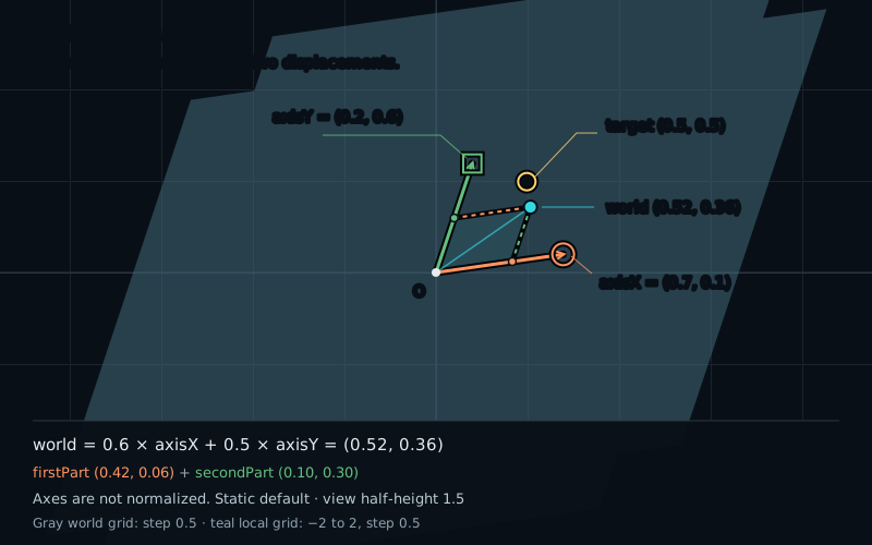
Pull an axis endpoint. The grid leans or stretches, and a point moves with it. Its local coordinates stay the same. Our job is to explain where the point goes using two scaled arrows.

Axis X=(0.7,0.1), axis Y=(0.2,0.6), and local coordinates (0.6,0.5). The two contributions (0.42,0.06) and (0.1,0.3) add to world position (0.52,0.36).
Two local coordinates → two scaled axes → one world point0.6 × (0.7, 0.1) + 0.5 × (0.2, 0.6) = (0.52, 0.36)

We have used X and Y as if their meaning were fixed. On our diagrams, one unit of X points right and one unit of Y points up. That is a useful choice, but it is still a choice. A coordinate pair needs a pair of reference axes before it describes a position.

Start with familiar axes

Take the point (0.6,0.5). In the usual coordinate system, we reach it by moving 0.6 units right and 0.5 units up. Write those two unit steps as vectors:

vec2 axisX = vec2(1.0, 0.0);
vec2 axisY = vec2(0.0, 1.0);
vec2 local = vec2(0.6, 0.5);
vec2 world = local.x * axisX + local.y * axisY;
// (0.6, 0.0) + (0.0, 0.5) = (0.6, 0.5)

This looks like extra work because the result has the same numbers as the input. But it exposes what the coordinates mean: each number scales one chosen step, then we add the resulting displacements.

We will call the fixed coordinates of the drawing world coordinates. The coefficients attached to our movable axes are local coordinates. Both systems share the origin in this chapter. We are changing the axes, not moving the origin.

Choose different steps

Now give each local axis a new direction and length, measured in world coordinates:

vec2 axisX = vec2(0.7, 0.1);
vec2 axisY = vec2(0.2, 0.6);

One local X step now moves 0.7 world units right and 0.1 up. One local Y step moves 0.2 right and 0.6 up. The axes do not have to be perpendicular, and their lengths do not have to match.

These two independent directions form a basis for the plane. They give us two building blocks for describing any displacement. Their order matters: the first belongs to local.x, the second to local.y.

Do not normalize these vectors. Their lengths are part of the coordinate system. If we double axisX, one local X unit covers twice as much world distance. Normalizing would discard that choice.

Add the two parts

Keep the local coordinates at (0.6,0.5). Scale each axis separately:

vec2 firstPart  = local.x * axisX; // (0.42, 0.06)
vec2 secondPart = local.y * axisY; // (0.10, 0.30)
vec2 world = firstPart + secondPart; // (0.52, 0.36)

Draw the first contribution from the origin. From its endpoint, draw the second contribution without rotating it. Their combined route ends at the world point. Reversing the order of the two additions reaches the same place; the four endpoints form a parallelogram.

This is vector scaling and addition from chapter 02, used as a coordinate system. The local numbers are coefficients. The axis vectors carry the world displacement for each local unit.

A negative coefficient reverses its contribution. For local = (-0.6,0.5), the first part is (-0.42,-0.06), so the world result becomes (-0.32,0.24). A zero coefficient removes one part; it does not remove that axis from the coordinate system.

The same rule builds the grid. Hold one local coordinate fixed and vary the other: the world points trace a straight line parallel to the corresponding axis. Repeat for several fixed values and the two families of lines make a tilted grid.

Try three test points

Before working with an arbitrary coordinate pair, test three simple inputs. Each one tells us something directly about the chosen axes:

For axisX=(0.7,0.1) and axisY=(0.2,0.6)
Local coordinatesWorld expressionWorld result
(1,0)axisX(0.7,0.1)
(0,1)axisY(0.2,0.6)
(1,1)axisX + axisY(0.9,0.7)

The first two inputs land at the axis endpoints. The third reaches the opposite corner of their unit parallelogram. The local origin (0,0) always stays at the world origin because both contributions are zero.

These small tests also catch swapped axes. If (1,0) lands on the endpoint meant for Y, the code has attached the first coordinate to the wrong vector. We will reuse this check when we put the axes into a matrix.

Keep the point, change the numbers

Changing the basis while keeping the local coordinates fixed usually moves the point. Keeping the world point fixed requires a different question: which local coefficients reach it using the new steps?

Use the gold target at world position (0.5,0.5). The ordinary axes reach it with local coordinates (0.5,0.5). Now try:

vec2 axisX = vec2(0.5, 0.0);
vec2 axisY = vec2(0.25, 0.5);

Only the Y step contributes to world height. We need one whole Y step to reach height 0.5. That also moves us 0.25 right. The remaining 0.25 of horizontal distance needs half an X step. Our new coordinates are therefore (0.5,1.0):

0.5 * vec2(0.5, 0.0) + 1.0 * vec2(0.25, 0.5)
// (0.25, 0.0) + (0.25, 0.5) = (0.5, 0.5)

The world point has not changed. Its description has. This is why a pair of coordinates without its basis is incomplete information.

Do not assume that dotting the world vector with each new axis recovers its local coordinates. The projection from chapter 06 measures a component along a direction. Our axes can overlap in direction and have different lengths. For the default example, the two raw dots are (0.4,0.32), not (0.6,0.5). General recovery needs a separate calculation, which we will develop later.

When the axes collapse

Suppose both axes point along the same line. Any sum of their multiples remains on that line. We can still run the formula, but we no longer have a basis for the whole two-dimensional plane.

For axisX=(0.6,0.3) and axisY=(1,0.5), local (1,0) and (0,0.6) both reach (0.6,0.3). Coordinates are no longer unique, and a point off that line cannot be reached at all.

A zero axis also removes a direction; two zero axes send every input to the origin. Nothing requires division in our forward formula, so these cases remain safe to draw. Nearly parallel axes still form a basis if they are independent, though recovering coordinates becomes sensitive. We will examine that distinction in chapter 15.

Try it

Build the point from two steps.

LIVE GLSL / WEBGL 2

Move an axis endpoint while keeping the local coordinates fixed. Follow the two contributions to the resulting point. Show original grid compares the fixed world grid with the grid made by your axes.

This chapter uses a fixed view from −1.5 to 1.5 world units vertically, giving unit-axis endpoints room to breathe. One world unit occupies a third of the canvas height on both axes. Values are not rescaled or normalized.

Static default basis: axis X=(0.7,0.1), axis Y=(0.2,0.6), local=(0.6,0.5). The contributions (0.42,0.06) and (0.1,0.3) add to world=(0.52,0.36). The fixed gold target is (0.5,0.5).
Orange circle: axis X handleGreen square: axis Y handleCyan: world pointGold ring: target (0.5,0.5)

Fixed view half-height: 1.5. Equal coordinate units; y runs from −1.5 to 1.5. One unit is one third of the canvas height.

Small solid orange and green markers show firstPart and secondPart. Dashed translated copies complete their parallelogram. The faint gray grid is the original coordinate grid; colored grid lines follow the edited axes.

The mapped grid is a finite local patch: −2 to 2 on both local axes, every 0.5. Each segment endpoint is combined forward. Parts of this finite patch may lie outside the fixed view.

Axes and local components

Axis X · full vector
Axis Y · full vector

Axis components range from −1 to 1. The shader uses the complete vectors: their lengths are not normalized.

These axis presets keep the current local components. Zero X keeps axis Y; Zero both sets both axes to zero.

Local components · how much of each axis

Local presets keep the axes. Local components range from −2 to 2.

Target exercise sets X=(0.5,0), Y=(0.25,0.5), local=(0.5,0.5). Adjust the local components by hand to reach the fixed gold ring. Reset lab restores controls; Reset code restores the shader.

Preparing the live shader.

Axis X · full vector
(0.70000, 0.10000)
Axis Y · full vector
(0.20000, 0.60000)
Axis lengths · |X|, |Y|
0.70711, 0.63246
Local components · local
(0.60000, 0.50000)
firstPart · local.x × axisX
(0.42000, 0.06000)
secondPart · local.y × axisY
(0.10000, 0.30000)
World point · firstPart + secondPart
(0.52000, 0.36000)
Distance to target · |world − (0.5,0.5)|
0.14142

These two axes span a two-dimensional plane. Their lengths are part of the forward combination.

The world point is inside the fixed view.

Readouts are host float32 reference calculations for the built-in forward combination, not GPU measurements. Shader edits do not change them; the last digits may round differently on the GPU. The axis diagnostic uses the same float32 input vectors and a relative near-parallel tolerance of 0.000001. It never modifies the axes or the point.

Drag either hollow axis handle. Clicking near a handle selects it; clicking elsewhere places the selected handle there, within the component limits. The Move handle menu chooses X or Y explicitly. Focus the diagram and press arrow keys to move that endpoint by 0.05 world units, or Shift for 0.25. On touch screens, tap to place the selected handle or use the controls; a swipe scrolls the page.

Open the complete shader edit · run · reset

The host supplies the full axes, the local components, both grid toggles, and the drawing-buffer size. The lesson is the three lines that compute firstPart, secondPart, and world. All segment, arrow, and grid drawing helpers are supplied here.

⌘ / Ctrl + Enter to run

The local grid is a finite patch: coordinates from −2 to 2 in steps of 0.5. Its segments are built by the same forward formula as the point; no inverse transform is hidden in the drawing. The complete host code supplies the axes and local coordinates.

A complete construction shader

This smaller shader draws the axes, the contribution parallelogram, and the point. Paste it into the editor; the controls still work. The longer default shader adds axis handles and the local grid. Its surrounding interface labels the construction.

#version 300 es
precision highp float;
uniform vec2 uResolution;
uniform vec2 uAxisX;
uniform vec2 uAxisY;
uniform vec2 uLocal;
uniform int uShowOriginalGrid;
out vec4 fragColor;

float segmentDistance(vec2 p, vec2 a, vec2 b) {
    vec2 ab = b - a;
    float lenSq = dot(ab, ab);
    float t = lenSq > 0.00000001
        ? clamp(dot(p - a, ab) / lenSq, 0.0, 1.0) : 0.0;
    return length(p - (a + t * ab));
}

float stroke(float distanceToLine, float width, float edge) {
    return 1.0 - smoothstep(width, width + edge, distanceToLine);
}

void main() {
    // Fixed view half-height: 1.5 world units; equal units on both axes.
    vec2 p = 1.5 * (2.0 * gl_FragCoord.xy - uResolution) / uResolution.y;
    float edge = 3.0 / uResolution.y;
    vec2 firstPart = uLocal.x * uAxisX;
    vec2 secondPart = uLocal.y * uAxisY;
    vec2 world = firstPart + secondPart;
    vec3 color = vec3(0.04, 0.06, 0.09);
    if (uShowOriginalGrid == 1) {
        vec2 grid = abs(mod(p + 0.25, 0.5) - 0.25);
        color = mix(color, vec3(0.24, 0.29, 0.34),
                    stroke(min(grid.x, grid.y), 0.0, edge));
    }
    float axes = min(segmentDistance(p, vec2(0.0), uAxisX),
                     segmentDistance(p, vec2(0.0), uAxisY));
    color = mix(color, vec3(0.65), stroke(axes, 0.008, edge));
    float xParts = min(segmentDistance(p, vec2(0.0), firstPart),
                       segmentDistance(p, secondPart, world));
    float yParts = min(segmentDistance(p, vec2(0.0), secondPart),
                       segmentDistance(p, firstPart, world));
    color = mix(color, vec3(1.0, 0.57, 0.28), stroke(xParts, 0.012, edge));
    color = mix(color, vec3(0.40, 0.87, 0.56), stroke(yParts, 0.012, edge));
    float targetRing = abs(length(p - vec2(0.5, 0.5)) - 0.055);
    color = mix(color, vec3(1.0, 0.81, 0.31), stroke(targetRing, 0.006, edge));
    color = mix(color, vec3(0.24, 0.88, 0.94),
                1.0 - smoothstep(0.035, 0.035 + edge, length(p - world)));
    fragColor = vec4(color, 1.0);
}

The view multiplier changes only which world positions fit on screen. It does not change the axis vectors, the local coefficients, or their world result. Large combinations can leave the visible window; the numeric result remains available.

Your turn

Use Reset lab and Reset code.

  1. With the default axes, predict the world points for local (1,0), (0,1), and (1,1). Use the local presets to check. Then enter (-0.6,0.5) and explain the two contributions.
  2. Use Identity and enter local (0.5,0.5) to reach the fixed gold target. Then choose Target exercise. Change only the local coordinates until you reach that same target again; do not move the axes.
  3. Choose Stretched and predict how many local Y units are needed to reach world height 0.5. Choose Swapped and predict where local (1,0) will go.
  4. Choose Collinear. Compare local (1,0) and (0,0.6), then try to reach the gold target. Explain why the forward formula still works even though the axes no longer describe a full plane. Try Zero X and Zero both as well.
A hint

For the target exercise, solve the height first. Only axisY contributes to it. Then work out how much horizontal distance remains for axisX. A grid that collapses to a line cannot reach a target away from that line.

Check your result

The default test points are (0.7,0.1), (0.2,0.6), and (0.9,0.7). Negative local X gives world (-0.32,0.24). Identity reaches the target with local (0.5,0.5); Target exercise needs (0.5,1). Stretched uses axisY=(0,0.5), so one local Y unit gives world height 0.5. Swapped sends (1,0) to (0,1).

Collinear maps both test inputs to (0.6,0.3), on the line world.y=0.5×world.x. The gold target (0.5,0.5) is off that line. A zero X axis makes local.x irrelevant, and two zero axes give world (0,0) for every input.

What you can do now

Predict the images of (1,0), (0,1), and (1,1), and reach the same world point using two different bases. You can explain what each local number multiplies, including with tilted or unequal axes. Next, we will store these two vectors as the columns of a matrix.