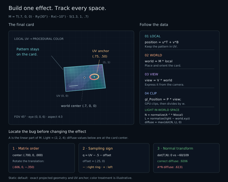
Move the pointer across the card. Its surface tilts, the pattern travels with it, and the light changes. This is a small interface effect, but it brings together almost every space we have used in the book.
Take the finished effect apart
Start at Finished, then choose the four build stages in order. Shape shows the local pattern on a centered, front-facing card. Transform adds scale, rotation, translation, and pointer tilt. Camera lets you change the viewpoint and vertical field of view. Light adds world-space diffuse lighting.
At each step, predict which part of the image should change. Moving the camera should not slide the pattern across the surface. Changing the light should not move the card. That separation is the new skill: when something looks wrong, identify the space where it first became wrong.
Give every value an address
We keep one mesh, one camera, and one point light. Before adding color, write down the meaning of the values that cross the shader stages:
| Value | Space and purpose |
|---|---|
| aPosition, aNormal | Local mesh position and surface normal. |
| aUV, vUV | Dimensionless material coordinates, from 0 to 1 across the card. |
| vWorldPosition | Position after the model transform, before the camera. |
| vWorldNormal | Normal transformed into world space, still awaiting normalization. |
| uLightPosition | Point light position in the same world space. |
| gl_Position | Homogeneous clip position, before the GPU's perspective divide. |
The card uses the tilted local plane from chapter 21: T=(1,0,1)/sqrt(2), B=(0,1,0), and N=(−1,0,1)/sqrt(2). Its points are u*T+v*B, with u from −1 to 1 and v from −0.64 to 0.64. Four corners and two triangles are enough.
This initial tilt has a useful purpose. Non-uniform X/Z scale visibly separates the correct normal from the ordinary direction transform. On an axis-aligned XY card scaled along XYZ, those two normalized results could agree and hide our prepared mistake.
Keep the ink on the card
The pattern reads vUV, carried from the mesh through perspective-correct interpolation. It never reconstructs its coordinates from gl_FragCoord. Rotating the card therefore carries its material with it, including when the two triangles recede by different amounts.
Let local=vUV−0.5. These centered UV coordinates run from −0.5 to +0.5 along each material axis. To place an accent a quarter of the card's width to the right, sample its shape at local−vec2(0.25,0.0). The accent's center occurs where that sample is zero: UV=(0.75,0.5).
vec2 local = vUV - 0.5;
vec2 accent = local - vec2(0.25, 0.0);
This is the backward mapping from chapter 14. Subtracting the desired offset moves the visible shape right. Adding it places the center at UV=(0.25,0.5), on the left. UV units describe fractions of the material; they are not equal physical distances on this rectangular card. A circular UV motif can consequently appear elliptical on the surface.
Move the object in the intended order
The finished model is T*Ry*Rx*S. With column vectors, the rightmost operation acts first: scale the local mesh, pitch around X, yaw around Y, then translate its center to (0.7,0,0). GLSL matrices use columns, and every forward position transform multiplies the vector on the right.
mat4 model = uTranslation * uRotation * uScale;
vec4 world = model * vec4(aPosition, 1.0);
gl_Position = uProjection * uView * world;
The default scales are sx=1.3, sy=1, sz=0.7, followed by pitch −10° and yaw 30°. The center remains (0.7,0,0) as those angles change. Swapping translation and rotation gives R*T*S, rotating the translation as well. At the default angles, the center becomes approximately (0.60622,0,−0.35). The card starts orbiting instead of turning around its own translated center.
Shape uses a separate neutral setup: unit scale, no translation, and Ry(45°). That rotation maps our tilted T to +X and N to +Z, so the card faces the camera. Later stages activate the model controls; disabled controls do not affect the current stage.
Use the pointer as a small rotation control
Convert the pointer's CSS-pixel position within the canvas to fractions of its displayed width and height. Map those fractions to centered values from −1 to +1, with Y pointing upward. They supply at most 15° of extra yaw and pitch around the manual angles.
This is a control mapping, not a point picked on the 3D surface. It needs neither a ray nor a plane intersection. Keyboard angle controls provide the same kind of adjustment. Pause pointer freezes pointer response; the manual controls remain available for inspection. Rendering happens when something changes, with no idle animation loop.
The camera uses the look-at construction from chapter 19, with eye=(cameraX,0,6), target=(0,0,0), and world up +Y. Camera X changes both the eye and the viewing basis. Merely subtracting a different X offset would move a camera that still looked parallel to its old direction.
The perspective matrix from chapter 20 uses the actual drawing-buffer aspect ratio, vertical FOV, near=0.5, and far=12. Resize updates that aspect; it does not stretch the material to fill the canvas. A real model scale may intentionally change the card's proportions. A viewport resize should add no extra distortion.
Compare directions in one space
Let A be the model's linear 3×3 part. Transform tangents with A and normals with transpose(inverse(A)), then normalize the interpolated normal in the fragment shader. The host caches this normal matrix while the model stays unchanged. Translation does not affect it.
// Normalize only after the squared-length guard shown below.
vec3 N = normalize(vWorldNormal);
vec3 L = normalize(uLightPosition - vWorldPosition);
float diffuse = max(dot(N, L), 0.0);
Both N and L are world-space directions. The light defaults to (2,2,4); its X control moves it independently of the camera. Positive scales keep the model invertible. A squared-length guard of 1e−8 returns zero before normalizing an undefined light direction, as in chapter 21.
At the default model, the correct unit normal is approximately (0.02296,0.15289,0.98798). Its dot with the unit transformed tangent is zero apart from rounding. The ordinary A*N transform gives approximately (−0.52906,0.08233,0.84458), and its tangent dot is −60/109≈−0.55046. Unit length has not repaired perpendicularity.
The finished material combines fixed ambient brightness with diffuse light. Its border, color bands, and accent are artistic decoration, not another lighting model. There are no shadows, distance attenuation, environment reflections, or physically based specular highlights.
Find the first broken space
Use Local to inspect UV attachment, World to inspect positions after the model, and Normal to display 0.5+0.5*N. World view uses clamp(0.5+0.2*worldPosition,0,1), with each channel corresponding to X, Y, or Z. The normal view maps signed components into RGB; a flat card has one normal color. These are diagnostic colors, not light intensity.
The three bug presets deliberately change one expression each. For the order bug, inspect the center in World view. For the sampling bug, return to Material and compare the accent against Local coordinates. For the normal bug, use Normal and the tangent-dot reference. Repair the marked line in the shader editor, run it, and compare the picture again.
Numerical readouts describe the built-in reference model. They do not read your edited GPU program. After a code repair, the reference can still describe the injected error while your shader shows the corrected result. Use it as a prediction, then clear the injection to compare against the correct built-in image.